RECORDING
--------------------------------
• Switch on the source component (tuner, amplifier, etc.).
• Set the TAPE MONITOR switch on your amplifier or receiver to the SOURCE position.
o
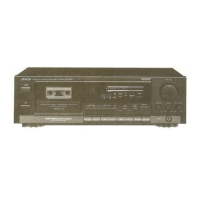
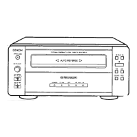
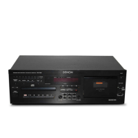
DErilON "RECISIO~ AUDIO COMPONENT/ST'IIED CASSETTE TAPE DEe!<:00101-600'"
W~EB~~:S~:l~~OI
Oc::JO
3HEAO
CERAMIC COMPOSITE CASSETTE STABILIZER
VIBRATION ABSORBING t.lECHANISM
~_-~_4~-~-3~~m"4q'5'1'~
~ .
""A~ •••••O l'!
nPc Pc DI1 a:~:cT1!~;~~:~::u~I 7'': 1
fbO~fbor::
~l'Eo.o:'J<!yFLTEKTyP£-IV Oou:c ~
~[I""""II
Co
·O:~~;,~Q:
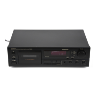
o POWER
Push the switch to turn "ON" (.--) the power.
f} EJECT
Press the EJECT button to open the cassette compart·
ment.
e Cassette Compartment Cover
When a cassette tape is inserted and the door is closed,
the tape is automatically wound up for about 0.2 sec.
to eliminate the slack. (Confirm that the claw of the
cassette half is not broken.)
e DOLBY NR
Set, in accordance with the recording to be made.
For recordings without Dolby NR, set to "OFF". For
recordings with Dolby B NR, set to "ON" and "B" (The
B·TYPE indicator will light up). For recordings with
Dolby C NR, set to "ON" and "C" (The C·TYPE indicator
will light up). Future mistakes during playback can be
avoided if the cassette is so marked for Dolby NR
encoded recordings .
• MPX FILTER
Button it "ON" for the DOLBY NR recording of FM
broadcasts (The FILTER indicator will light up).
o OREC/REC MUTE
When pressed, the deck goes into the record standby
mode. The OREC and ODPAUSEindicators will light
up, and both recording/playback and erase heads will
come into contact with the tape. Initial setting of
recording levels should be made in the record standby
mode. (The source monitor mode comes automatically.)
8 INPUT LEVEL
Used to set the recording level.
o BALANCE
Adjust the recording level balance between the left
and right channels.
o ~PLAY
When pressed, the recording will start.
The C>PLAY and OREC indicators will light up.
(The tape monitor mode comes automatically.)
• When recording is finished, press the STOP (IISTOP)
button.
PROPER RECORDING LEVEL _
A too high recording level can saturate the tape and cause distortion. On the other hand, if recording levels are set
too low, soft passages will be marked by residual noise. Proper recording level is the single most important factor for
making well balanced recordings.
The tape select indicators- TYPE-I, TYPE-II and TYPE· N provide guidelines for the maximum allowable recording levels
for each tape type. Adjust the INPUT LEVEL controls while checking the FL PEAK METER.
Guideline for maximum recording level
Normal tape
+ 1 dB levels on peaks
(TYPE
[ )
Cr02 tape
+ 3 dB levels on peaks
(TYPE II)
I
Metal tape
+5 dB levels on peaks
(TYPE IV)
Note: Optimum recording levels can differ depending
on program sources or the type of tape used.
Make trial recordings using the simultaneous
monitoring. Refer to the description under
"MONITOR BUTTON".
6
• Meter reading difference between Land R channels
The left and right channels readings of the PEAK METER can differ due to variations in input signal levels. In such ~
cases, adjust the individual channels of the BALANCE control until identical meter readings are obtained for both channels.