15
15UD-M31
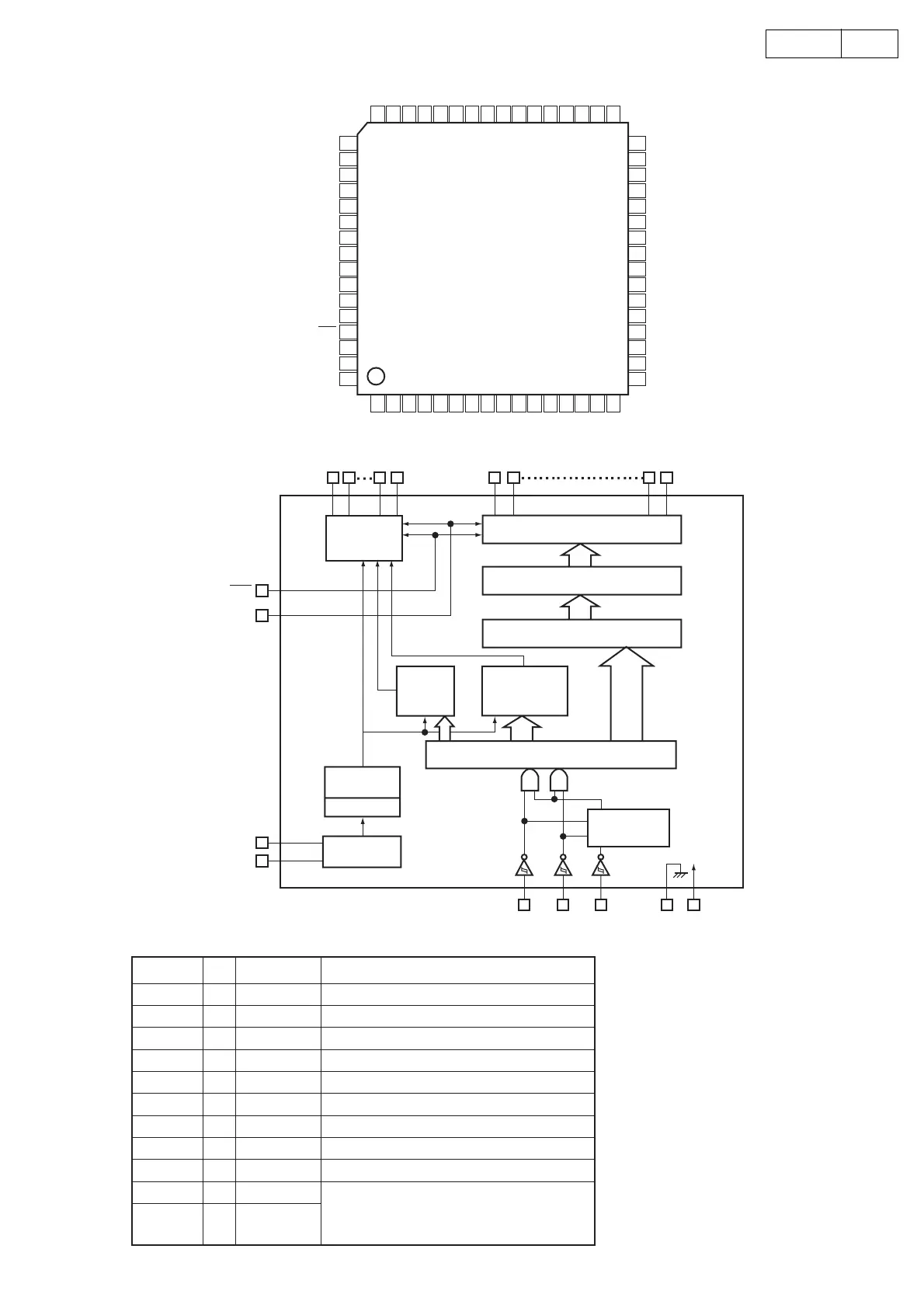
LC75725E(IC401)
Terminal Function
Pin No. I/O Name Function
1,13 Power supply pin to driver block
2~12 Digit output pin
14~56 Segment output pin
57 power supply pin
63
64
CE : Chip enable
CL : Sync clock
DI : Transfer data
1 2 3 4 5 6 7 8 9 10111213141516
48 47 46 45 44 43 42 41 40 39 38 37 36 35 34 33
64
63
62
61
60
59
58
57
56
55
54
53
52
51
50
49
17
18
19
20
21
22
23
24
25
26
27
28
29
30
31
32
S25
S26
S27
S28
S29
S30
S31
S32
S33
S34
S35
S36
S37
S38
S40
S41
S42
S43
VFL
G11
G10
G9
G8
G7
G6
G5
G4
G3
G2
G1
VFL
S24
S23
S22
S21
S20
S19
S18
S17
S16
S15
S14
S13
S12
S11
S10
S9
S39
S8
S7
S6
S5
S4
S3
S2
S1
Vss
OSC0
OSC1
V
DD
BLK
CE
CL
DI
DIGIT
DRIVER
SEGMENT DRIVER
MPX
LATCH
DIMMER
TIMING
GENERATOR
GRID
CONTROL
SHIFT REGISTER
ADDRESS
DETECTOR
TIMING
GENERATOR
DIVIDER
CLOCK
GENERATOR
V
DD
VSS
CE
CL
DI
OSCI
OSCO
VFL
BLK
G11
G10
G2
G1
S43
S42
S2
S1
-
O
O
-
O
I
-
I
I
I
I
58 OSCO Pin for oscillator
59 OSCI Pin for oscillator
60 V
DD Power supply pin to ligic block
61 BLK Display off input pin
62 CE Input for serial data transfer
V
FL
G1~G11
S1~S43
Vss
CL
DI
 Loading...