EasyManua.ls Logo

Denon UD-M31 Service Manual

Denon UD-M31
45 pages
To Next Page IconTo Next Page
Page #1 background imageLoading...
Page #1 background image
SERVICE MANUAL
MODEL
UD-M31
STEREO CD RECEIVER
Some illustrations using in this service manual are slightly different from the actual set.
16-11, YUSHIMA 3-CHOME, BUNKYOU-KU, TOKYO 113-0034 JAPAN
Telephone: 03 (3837) 5321
X0164V.02 DE/CDM 0302
For Europe & U.K. model
Version 2
Question and Answer IconNeed help?

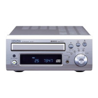
Do you have a question about the Denon UD-M31 and is the answer not in the manual?

Denon UD-M31 Specifications

General IconGeneral
BrandDenon
ModelUD-M31
CategoryCar Receiver
LanguageEnglish

Summary

Safety Precautions

Leakage Current Check

Check for leakage current or line to chassis resistance before returning the unit.

Disassembly Procedure

Top Cover Removal

Steps to remove the top cover of the unit.

Front Panel Removal

Steps to detach the front panel.

CD Mechanism Unit Removal

Procedure for removing the CD mechanism unit.

Rear Panel and PWB Removal

Rear Panel Removal

Steps to remove the rear panel.

Main PWB Removal

Procedure to detach the main PWB.

Display PWB Removal

Steps to remove the display PWB.

Block Diagram Overview

Level Diagram and Signal Flow

CD Test Mode Operations

Setting and Button Explanations

Guide to setting the CD test mode and button functions.

Test Mode Functional Checks

Disc Discrimination and Adjustment

Procedure for disc discrimination and adjustment in test mode.

Servo State Verification

Steps to check servo states like laser, focus, and tracking.

Waveforms Analysis

Semiconductor Component Details

IC201 Pin Assignment and Function

Pinout and detailed functions for IC201 (μPD784216AGC-8EU).

IC Pinout and Function Details

IC201 Terminal Function (Continued)

Continuation of pinout and functions for IC201.

IC Pinout and Function Details (Continued)

IC201 Terminal Function (Final)

Final part of pinout and functions for IC201.

IC803 Block Diagram and Pinout

LC78625E Block Diagram

Functional block diagram for the LC78625E IC.

LC78625E Pin Assignment

Pin numbers and assignments for the LC78625E IC.

LC78625E Terminal Functions

LC78625E Pinout Details

Detailed pinout and functions for LC78625E.

LC78625E Terminal Functions (Continued)

LC78625E Pinout Details (Final)

Final part of pinout and functions for LC78625E.

IC401 Component Details

LC75725E Pin Assignment

Pin assignment for the LC75725E IC.

LC75725E Terminal Function

Pinout and functions for the LC75725E IC.

IC802 Component Details

LA9241M Pin Assignment

Pin assignment for the LA9241M IC.

LA9241M Terminal Function

Pinout and functions for the LA9241M IC.

LA9241M Terminal Function (Continued)

LA9241M Pinout and Functions

Continuation of pinout and functions for LA9241M.

IC801 Component Details

LA6559 Pin Assignment

Pin assignment for the LA6559 IC.

LA6559 Pinout and Functions

Pinout and functions for the LA6559 IC.

IC302 and IC303 Component Details

LC75342M Pin Assignment

Pin assignment for the LC75342M IC.

LC72720NM Block Diagram and Pinout

Block diagram and pin functions for LC72720NM IC.

Component Views and Block Diagrams

STK402-050 Front View

Component view of the STK402-050 IC.

BA6287F Block Diagram

Block diagram for the BA6287F IC.

93LC66 Block Diagram

Block diagram for the 93LC66 IC.

M51957BFP Top View

Component view of the M51957BFP IC.

FL Display Component Details

FL Display Grid Assignment

Grid assignment for the FL display.

FL Display Pin Connection

Pinout and connection details for the FL display.

Printed Wiring Board Layouts

Main Unit Component Side

Component layout of the 1U-3498 Main Unit.

Main Unit Foil Side

Foil layout of the 1U-3498 Main Unit.

Printed Wiring Board Foil Layout

Main Unit Foil Side (Continued)

Continued foil layout of the 1U-3498 Main Unit.

CD Unit Layouts

CD Unit Component Side

Component layout of the 1U-3507 CD Unit.

CD Unit Foil Side

Foil layout of the 1U-3507 CD Unit.

Parts List Usage Notes

Resistor and Capacitor Notations

Explanation of resistor and capacitor type codes and notations.

PWB Parts List

Semiconductors Group

List of semiconductor components on the PWB.

Resistors Group

List of resistor components on the PWB.

PWB Parts List (Continued)

Resistors Group (Continued)

List of resistor components on the PWB.

PWB Parts List (Continued)

Resistors Group (Continued)

List of resistor components on the PWB.

PWB Parts List (Continued)

Capacitors Group

List of capacitor components on the PWB.

PWB Parts List (Continued)

Capacitors Group (Continued)

List of capacitor components on the PWB.

PWB Parts List (Continued)

Other Parts Group

List of miscellaneous components on the PWB.

Screw Types

List of screw types and quantities.

CD PWB Parts List

Semiconductors Group

List of semiconductor components on the CD PWB.

Resistors Group

List of resistor components on the CD PWB.

CD PWB Parts List (Continued)

Resistors Group (Continued)

List of resistor components on the CD PWB.

Capacitors Group

List of capacitor components on the CD PWB.

CD PWB Parts List (Continued)

Capacitors Group (Continued)

List of capacitor components on the CD PWB.

CD PWB Parts List (Continued)

Other Parts Group

List of miscellaneous components on the CD PWB.

Exploded View

Parts List for Exploded View

Illustrated exploded view of the unit's parts.

Exploded View Parts List

Remarks Key for Parts List

Key for remark symbols used in the parts list.

Main PWB Unit Parts

List of parts for the main PWB unit.

CD PWB Unit Parts

List of parts for the CD PWB unit.

Exploded View Parts List (Continued)

Screw Types List

List of screw types and quantities.

CD Mechanism Exploded View

Parts List for CD Mechanism

List of parts for the CD mechanism unit.

Packing and Accessories List

Packing List

List of packing materials and accessories.

Wiring Diagram

Schematic Diagram Notes

Related product manuals