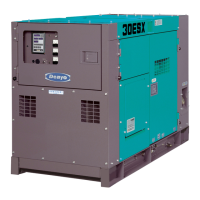
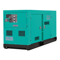
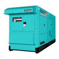
This document outlines the operation, maintenance, and specifications for the Denyo DCA-30ESX and DCA-40ESX diesel generator sets.
Safety Precautions
The manual emphasizes safety through various warnings and cautions. It highlights the importance of understanding symbols for hazard, unsafe practice, severe injury, or death (WARNING) and for hazard, unsafe practice, personal injury, or property damage (CAUTION). Users are instructed to observe all safety items, ensure proper explanation to outsiders, and avoid modifying the machine or using unauthorized parts to maintain warranty.
Safety labels are affixed to the machine, and users must keep them clean. If labels are damaged or lost, replacements should be requested from the distributor, specifying the nameplate number.
Engine Exhaust: Engine exhaust can be fatal due to lack of oxygen or poisoning by exhaust gases. Insufficient ventilation is a major risk. The machine should not be used in poorly ventilated areas or where exhaust gases may accumulate, such as indoors, in storehouses, tunnels, ships, or tanks. If used in confined spaces, the exhaust pipe must be extended to a well-ventilated area, and a ventilator should be used. Exhaust outlets should not be directed towards pedestrians or houses.
Electric Shock: Electric shock can be fatal. Output terminals should not be touched during operation. If hands or the machine are wet, touching terminals can result in death or serious injury. Wiring work requires turning off the circuit breaker and stopping the machine. The output terminal cover must remain closed, and terminal bolts tightened during operation. Even at low idle speed, a low voltage is generated. All electrical parts should be avoided during operation. The control panel and side door must be closed and locked during operation. When opening the control panel for voltage selection, the circuit breaker must be turned off, and the machine stopped. Improper grounding can lead to electric shock, so grounding of the machine and load must follow local rules.
Moving Parts: Moving parts can cause severe injury. The rotary unit, which runs at high speed, is dangerous to touch. Doors must be closed and locked during operation. If a door needs to be opened, hands and head should be kept away from moving parts to prevent injury. All checks and maintenance must be performed with the machine stopped.
Diesel Fuel: Diesel fuel is flammable and can cause fire or explosion. Flammable objects (paper, wood chips, oil, powder) should be kept away from the machine. Spilled fuel and oil must be wiped off.
Hot Coolant: Hot coolant can cause severe scalds. The radiator cap should not be opened when the water temperature is high, as steam or hot water may spout out. During operation or immediately after stopping, the radiator cap should not be opened while the water temperature is high. Cooling water needs to be checked or supplied when the engine is cooled (50°C or less). The reserve tank's cooling water level should be checked, and if below the low limit, water should be supplied. The radiator cap should only be opened once a week to check if water is full. When closing the radiator cap, it must be turned fully clockwise to prevent evaporation of cooling water, which can damage the engine.
Hot Parts: Hot parts can burn skin. High-temperature units are located in the machine. Care must be taken during operation. Inspection or maintenance requires stopping the machine in advance. Even after stopping, the bonnet remains hot, so wait until the engine cools sufficiently.
Stacking: Improper stacking can cause falling or dropping accidents. When stacking other machines, ensure the bonnet is free from damage, fixing bolts are tightened, and the machine is placed horizontally on a solid foundation that can withstand the weight. Machines can be stacked up to two stages, provided the stacked machines' weight and size are less than the base machine. Square timbers should be used to ensure even weight distribution. Machines should not be operated while stacked.
Battery: Batteries generate flammable gases, and improper handling can lead to explosion or serious injury. Charging should occur in a well-ventilated area to prevent gas accumulation and ignition. When connecting booster cables, terminals (+ and -) should not be jumpered, as sparks can ignite flammable gases. For maintenance, the ground cable should be disconnected. Battery acid is dilute sulfuric acid and can cause burns. If acid gets on clothes or skin, wash immediately with plenty of water. If it gets in eyes, wash immediately and consult a doctor, as it can cause blindness. The engine must be stopped before checking or handling the battery.
Operator Safety: Operators should not operate the machine if tired or under the influence of alcohol or drugs. Baggy clothes, necklaces, or other projections that can cause injuries should be avoided.
Noise: The machine generates loud noise when the door is open. Ear protectors should be worn during operation.
Connection to House Wiring: Before connecting to a building's electrical system, a licensed electrician must install an isolation (transfer) switch to prevent serious injury or death.
Transportation: The machine should not be lifted by the support hook or ladder, as they are not strong enough and could cause a falling accident. The hanger located at the roof center should be used for lifting. No one should be under the lifted machine. The machine should not be lifted or transported during operation, as this can damage the fan or cause serious trouble. When loading onto a truck, the machine must be firmly fixed with support hooks on both sides.
Construction
The generator features several key components:
- Oil drain plug
- Exhaust gas outlet
- Hanger rod
- Support hook
- Coolant inlet
- Output terminal
- Fuel inlet
- Fuel drain plug
- Coolant drain plug
- Engine indicator
- Operating panel
- Control panel
Internal components include:
- Air cleaner
- Oil filter
- Fuel filter
- Reserve tank
- AC generator
- Diesel engine
- Radiator
- Oil level gauge
- Control box
- Fuel tank
- Battery
The control panel includes:
- Frequency meter
- AC ammeter
- AC voltmeter
- Voltage regulator
- Circuit breaker (1-phase)
- Pilot lamp
- Panel light
- Earth leakage relay
- Engine indicator (engine speed, oil pressure, water temp, battery charging voltage, integrating time)
- Fuel level indicator
- Warning lamps
- Starter switch
- Preheat lamp
- Emergency stop button
- Throttle lever
- Frequency adjust screw
- Fuel priming pump button
- Panel light switch
Engine Indicators: The engine indicator displays numerical values for engine speed, engine oil pressure, run hours, battery charging voltage, and engine coolant temperature.
- Engine speed: Revolutions per minute, 1500min⁻¹ at 50Hz and 1800min⁻¹ at 60Hz.
- Engine oil pressure: 2 to 5 x 100 kPa at normal engine operation. Higher values indicate cold conditions. A warning/up operation indicates normal values.
- Battery charging voltage: More than 12.5V at engine running.
- Engine coolant temperature: Between 75 to 95 °C at engine running. If higher, disconnect all loads and decrease speed for cool-down.
Fuel Level Indicator: Green lights indicate fuel level. Red lights indicate low fuel. Replenish fuel when only one lamp is lit.
Alarm and Memory: Abnormal conditions (oil pressure, battery voltage, coolant temperature) cause blinking numbers on the indicator. Once corrected, the indication stops. If the engine stops urgently or manually due to an abnormal condition, the abnormal value is memorized and displayed upon restart. Pressing "RESET" for more than 5 seconds clears the abnormal indication.
Hour Meter: The hour meter displays total running hours ("ODD"), and two trip meters ("TRIP A" and "TRIP B") for specific periods. Trip meters can be reset by pushing the selector button for more than 1 second after selection. The hour meter has an internal rechargeable battery. It indicates hours even when the generator is off. If unused for long periods, the battery discharges. A 30-minute charge provides 30 minutes of indication, while a 3-hour charge provides more than 10 days of indication.
Generator Indicators:
- Frequency meter: Indicates output voltage frequency (50Hz or 60Hz).
- AC ammeter: Indicates AC current flowing into the load. Must remain below rated current. Current for each phase can be checked with the ammeter change-over switch.
- AC voltmeter: Indicates AC output voltage. Must remain at rated voltage.
Indication/Alarm Lamps:
- Preheat lamp: Lights up during preheating, then goes off.
- Warning lamps:
- High jacket water temperature (WATER TEMP): Lights up when water temperature rises abnormally. Emergency stop device activates.
- Oil pressure failure (OIL PRESS): Lights up during operation, emergency stop device activates.
- Air filter blinding (AIR FILTER): Lights up when air element is blinded. Element should be cleaned or replaced.
- High fuel filter water level (FUEL FILTER WATER LEVEL): Lights up when water level in fuel filter rises. Drain water from strainer.
- Over speed of engine (OVER SPEED): Lights up when engine speed rises abnormally. Emergency stop device activates.
Switches and Controllers:
- Starter switch:
- Stop: Engine stops.
- Run: Engine operates. Preheating system is energized, preheat lamp lights up, then goes off.
- Start: Engine starts. Key returns to "RUN" position automatically.
- Speed control device (Throttle lever): Controls engine speed. "START/IDLING" for startup/warm-up/cooling. "RUN" for constant speed operation (50Hz or 60Hz).
- Frequency adjusting screw: Adjusts frequency. "HIGH" increases, "LOW" decreases.
- Circuit breaker: Main switch for power supply. "ON" for operation, "OFF" for overload protection. If tripped, handle stops between ON and OFF. Push down to OFF, then ON.
- Fuel priming pump button: Vents air from fuel piping.
Transportation and Installation
Transportation:
- Do not lift by support hook or ladder. Use the hanger at the roof center.
- Keep clear of lifted machine.
- Do not transport during operation.
- Secure machine firmly with support hooks when loading.
Installation:
- Install horizontally on a solid foundation.
- Provide 1m space at control panel/fuel feed port, 1.2m on left/right for engine checks/cable connections.
- Ensure sufficient space above for hot air/exhaust gas discharge and water supply to radiator.
- In dusty/salty environments, maintain radiator and electrical parts carefully.
Indoor Installation:
- Exhaust gases must be discharged outdoors via an exhaust pipe.
- Exhaust air must be discharged outdoors via a duct.
- Insufficient indoor ventilation raises temperature and affects performance.
- Consult distributor for required ventilation volume.
Connecting the Load
Cables: Use cables of sufficient size. Overheating can damage cables. Select cable length and size to limit voltage drop to 5% of rated voltage. For 1-phase, 2-wire systems, voltage drop "e" is calculated as: e = (1/58) * (L/S) * I * 2, where L is length (m), S is cable thickness (mm²), and I is load current (A).
Electric Shock:
- Do not touch output terminals during operation.
- Turn off circuit breaker and stop machine for wiring.
- Close output terminal cover and tighten bolts during engine operation.
- Do not use damaged cables.
- Ensure connecting cables are normal and firmly connected.
Connection to House Wiring: A licensed electrician must install an isolation (transfer) switch.
Output Terminal Connection:
- Tighten locking bolts securely to prevent burning.
- Connect load to output terminal after confirming phase and voltage.
- Use O/U, O/V for 100/110V (50Hz/60Hz).
- Use U/V for 200/220V (50Hz/60Hz).
Precaution in Load Connection:
- Provide a switch to turn load ON/OFF between output terminal block and load.
- Stop engine and turn OFF breakers on control panel before connecting load.
- Do not contact connecting cable to output terminal of other phase on output terminal block.
- Close cover and tighten bolts when load connection is finished.
Earth Leakage Relay and Grounding:
- Electric Shock: Improper grounding can lead to death. The leakage protection device may not operate effectively.
- Grounding terminal for earth leakage relay, case grounding terminal, and load case must be grounded.
- The machine has an earth leakage relay (Mitsubishi Type NV-ZE, 30mA sensitivity, max 0.1s operating time) to detect leakage and cut off the circuit.
- Improper handling of the relay can be unsafe. Install a leakage relay for each load.
- Grounding:
- Ground the grounding terminal for earth leakage relay and case grounding terminal.
- Use grounding wire with sectional area 5.5mm² or larger.
- Attached grounding rod is usually sufficient, but if resistance is over 100 Ω, provide a larger rod.
- Ground load equipment similarly.
Precaution in Grounding:
- Select a shady, moist place for the grounding rod.
- Bury the grounding rod where pedestrians don't walk.
- If the lead wire is long, connect it via soldering or sleeve coupling.
- Avoid places within 2m of lightning conductor grounding location.
- Do not use a telephone set grounding conductor.
Operation Check (Leakage Relay):
- Start machine.
- Ensure all load-side breakers are "OFF".
- Set machine breaker to "ON".
- Press "TEST" button on leakage relay. If "LEAK" lamp (red) lights and breakers activate, relay is working.
- Press "RESET" button and return breaker to "OFF", then "ON".
- If relay activates, stop engine, measure insulation resistance, and repair leak before restarting.
Operation
Checking After Startup:
- Ensure all meters and lamps are normal (warning lamp off).
- Check exhaust gas color (colorless/light blue: normal; black: incomplete combustion; white: oil combustion).
- Check for unusual noise and vibration.
- Check earth leakage relay operation.
Adjustment During Operation:
- Set tachometer and frequency meter to rated by throttle handle.
- Set voltmeter to rated by voltage regulator.
- Note: Do not set throttle lever to "START/IDLING" or decrease speed by frequency adjusting screw during load operation, as this can cause voltage/frequency drop and device failure.
Shut Down:
- Turn OFF load circuit breaker.
- Turn OFF machine circuit breaker.
- Set throttle lever to "START/IDLING" for 5 minutes of cooling.
- Set starter switch to "STOP" to stop engine.
- Remove key.
- Check panel light is off.
- Check fuel amount and supply if necessary.
- Check for oil, fuel, and water leakage.
- Note: For emergency stop, push "EMERGENCY STOP" button until engine stops.
Protection Device: The machine has protection devices and emergency stop devices. If a running caution lamp lights, stop the engine immediately and resolve the cause.
- Oil pressure failure (OIL PRESS): Set point 130kPa (warning), 98.1kPa (stop).
- High jacket water temperature (WATER TEMP): Set point 97°C (warning), 105°C (stop).
- Battery charging failure: Set point 12.5V (warning).
- Overcurrent of generator: Device acts.
- Fuel level failure (FUEL LEVEL): Device acts.
- High fuel filter water level (FUEL FILTER WATER LEVEL): Device acts (30ESX only).
- Air filter blinding (AIR FILTER): Device acts.
- Earth leakage: Device acts (30mA sensitivity, 2070 min⁻¹ set point).
- Over speed of engine (OVER SPEED): Device acts.
- Abnormal values and units are indicated by lighting on and off.
Lubrication, Cooling Water, and Fuel
Engine Oil:
- Use specified engine oil (CD class or higher, API service).
- Recommended viscosity: SAE 10W-30 (all-season).
- Adjust viscosity based on ambient temperature (e.g., SAE 20 for -10°C to 10°C, SAE 30 for 0°C to 30°C, SAE 5W-20 for -30°C to 0°C, SAE 10W-30 for -20°C to 20°C, SAE 15W-40 for -10°C to 30°C).
- Do not mix different oil types.
- Replacement oil quantity: DCA-30ESX: 10.0L (0.3); DCA-40ESX: 13.2L.
Cooling Water:
- Use a mixture of good quality soft water (city water) and Long Life Coolant (LLC) with anti-freeze and anti-rust for aluminum radiators.
- LLC percentage: 30-50%. Below 30% reduces anti-rust effect; above 50% reduces anti-freeze effect.
- Recommended percentages: 30% for -10°C, 40% for -20°C, 50% for -30°C.
- For replenishment, use LLC of the same brand and density.
- Replace LLC every 2 years.
- Total cooling water quantity: DCA-30ESX: 10.9L (0.9); DCA-40ESX: 15.4L (1.0).
Fuel:
- Use #2 Diesel Fuel.
- Using other fuels or fuel containing water/dust deteriorates engine performance.
Handling of Battery
Caution:
- Battery generates flammable gases; improper handling can cause explosion/injury.
- Charge in a well-ventilated area.
- Do not jumper terminals (+ and -) with booster cables.
- Disconnect ground cable for maintenance.
- Battery acid is dilute sulfuric acid; improper handling causes burns.
- If acid contacts skin/clothes, wash with water. If in eyes, wash with water and consult doctor.
- Stop engine before checking/handling battery.
Caution on Battery Charge:
- Disconnect wiring cable from battery terminals before charging.
- When disconnecting, remove ground cable first.
- When connecting, connect ground cable last.
- Keep battery away from fire.
- Handle battery carefully to prevent electric sparks.
- If battery is overheated (liquid temperature above 45°C), stop charging.
- If battery is still charged but shows trouble: battery overheat, decrease in battery acid, deterioration of battery performance.
- Do not connect battery polarity in reverse.
Connection of Booster Cable:
- Connect booster cable "A" to (+) terminal of troubled machine.
- Connect other clip of "A" to (+) terminal of normal machine.
- Connect booster cable "B" to (-) terminal of normal machine.
- Connect other clip of "B" to engine block of troubled machine.
- Removal: Reverse order.
- Caution: Use appropriate size cables/clips. Normal machine battery capacity should match troubled machine. Ensure clips are firmly connected. Do not let (+) terminal touch (-). Connect to engine block more than 30cm from battery.
Periodical Checking and Maintenance
Refer to engine manual for engine system details.
Maintenance Schedule:
- Daily: Check oil level/stain, cooling water, fan belt, fuel/drain, battery acid level, water/oil leakage, bolts/nuts for looseness, exhaust color/sound/vibration, meters/warning lamps.
- 50 hours (first time): Replace engine oil, engine oil filter element.
- 250 hours: Replace engine oil (40ESX), clean air cleaner element, measure generator insulation resistance (monthly), check battery specific gravity.
- 500 hours: Replace engine oil (30ESX), engine oil filter element, fuel filter cartridge, clean radiator, inspect injection nozzle, check terminal/circuit connections. (Also includes 250-hour checks).
- 1000 hours: Clean inside fuel tank, replace air cleaner element, adjust fuel injection timing, check rubber suspension, nylon/rubber hose, lining. (Also includes 250- and 500-hour checks).
Checking/First 50 Hours:
- Engine oil replacement: Drain oil completely. Refill to "H" on dipstick.
- Engine oil filter element replacement: Remove cartridge with filter wrench. Clean filter base. Mount new cartridge, tighten 3/4 turn.
- Parts number (DCA-30ESX): Y06020 41214 (ISUZU), 897049-7081.
- Parts number (DCA-40ESX): Y06020 41217 (ISUZU), 113240-2322.
Checking/Every 250 Hours:
- Engine oil replacement: Refer to 8-2.(1).
- Air cleaner element cleaning: Remove element, clean with dry compressed air. Replace if damaged. Wipe off dirt before installing. Insert element completely.
- Measurement of insulation resistance: Use 500V insulation resistance tester monthly. Disconnect load side cable, turn ON circuit breaker, measure resistance between output terminal bolt and bonnet. If less than 1MΩ, check for leakage.
- Battery specific gravity check: If battery is discharged, measure specific gravity.
- Charging rate vs. liquid temp (°C) / specific gravity:
- 100% / 20°C: 1.28, 0°C: 1.29, -10°C: 1.30
- 90% / 20°C: 1.26, 0°C: 1.27, -10°C: 1.28
- 80% / 20°C: 1.24, 0°C: 1.25, -10°C: 1.26
- 75% / 20°C: 1.23, 0°C: 1.24, -10°C: 1.25
- If charging rate is below 75%, recharge.
Checking/Every 500 Hours:
- Fuel filter cartridge replacement: Remove cartridge, clean base, mount new cartridge, tighten 3/4 turn.
- Parts number (DCA-30ESX): Y06020 42700 (ISUZU), 898037-4800.
- Parts number (DCA-40ESX): Y06020 42407 (ISUZU), 113240-0791.
- Cleaning of radiator and intercooler: If fin or tube is blinded, clean with steam or high-pressure water. Keep 1.5m distance with high-pressure washer.
- Checking for terminal and connection of the circuit: Check for loosening, corrosion, burning.
Checking/Every 1000 Hours:
- Cleaning inside fuel tank: Drain fuel, wash out deposits and water.
- Replacement of air cleaner element: Replace element.
- Parts number (DCA-30ESX): Y06020 46366 (DONALDSON), P82-7653.
- Parts number (DCA-40ESX): Y06020 46365 (DONALDSON), P82-8889.
- Checking on rubber suspension: Check for damage or deformation. Replace if necessary.
- Checking on nylon and rubber hose: Check for hardening or deterioration. Replace if necessary.
- Checking on lining: Check for deterioration, oil stains, or removal. Replace if necessary.
Troubleshooting
Moving Parts: Rotary unit runs at high speed; stop machine for checks/maintenance.
Electric Shock: High voltage units; stop machine for checks/maintenance.
Hot Parts: High temperature parts; stop machine for checks/maintenance. Wait until cool.
Battery: Generates flammable gases; disconnect ground cable for maintenance.
Troubleshooting Table:
- Engine will not start up:
- Cell motor will not run: Discharged battery (charge/replace), detached/loosened/corroded battery terminal (repair), fuse blow (replace), improper starter switch (replace), improper starter (replace), broken lead wire (repair).
- Cell motor runs: Fuel shortage (supply), blinded fuel filter (replace element), air in fuel system (remove).
- Speed will not rise: Blinded fuel filter (replace element), compression failure (repair engine), blinded air cleaner (replace element).
- Engine stop by oil failure: Oil shortage (supply), oil pressure switch failure (replace), blinded oil filter (replace element).
- Over heat (water temperature): Cooling water shortage (supply), fan belt looseness (adjust), blinded core of radiator (clean), engine thermostat failure (repair).
- Voltmeter will not operate: Voltmeter failure (replace), AVR failure, burned ZNR (contact distributor/office), burned rotary rectifier (contact distributor/office), disconnected rotor wiring (contact distributor/office), burned generator wiring (contact distributor/office).
- Rated voltage will not be reached: Voltmeter failure (replace), AVR failure, VR failure (contact distributor/office), burned rotary rectifier (contact distributor/office), burned ZNR (contact distributor/office), burned generator wiring (contact distributor/office), low speed (increase).
- Voltage goes too high: Voltmeter failure (replace), AVR failure (contact distributor/office), VR failure (contact distributor/office).
- Applied load causes load voltage drop: Burned rotary rectifier (contact distributor/office), burned main field/exciter field wiring (contact distributor/office), unbalanced load (balance).
Long-term Storage
For long-term storage, choose a cool, moisture- and dust-free place.
- Clean machine thoroughly; repair peeled paint.
- Remove battery, charge completely, and recharge monthly.
- Check for defects and repair before future operation.
- Refer to engine manual for engine handling details.
Stacking:
- Improper stacking causes falling/dropping accidents.
- When stacking, ensure bonnet is undamaged, fixing bolts are tight.
- Place horizontally on a solid foundation.
- Stack up to 2 stages; stacked machines must be lighter/smaller than base.
- Use square timbers for even weight distribution.
- Do not operate machines while stacked.
Service Data
Specifications (DCA-30ESX / DCA-40ESX):
| Feature |
DCA-30ESX |
DCA-40ESX |
| Model |
DB-05071 |
DB-06071 |
| Frequency |
50/60 Hz |
50/60 Hz |
| Rated output |
24/30 kVA |
33/40 kVA |
| Rated voltage |
100/200 V / 110/220 V |
100/200 V / 110/220 V |
| Rated current |
120 A / 136 A |
165 A / 182 A |
| Power factor |
1.0 |
1.0 |
| No. of phases |
Single-phase (three wire) |
Single-phase (three wire) |
| Excitation |
Brushless type (with automatic voltage regulator) |
Brushless type (with automatic voltage regulator) |
| No. of poles |
4 |
4 |
| Speed |
1500/1800 min⁻¹ |
1500/1800 min⁻¹ |
| Insulation |
class F |
class F |
| Manufacture |
ISUZU |
ISUZU |
| Model |
BB-4JG1T |
BB-4BG1T |
| Type |
4-cycle water cooled, diesel engine, direct injection turbocharged |
4-cycle water cooled, diesel engine, direct injection turbocharged |
| No. of cylinders |
4 |
4 |
| Bore x stroke |
95.4 x 107 mm |
105 x 125 mm |
| Total displacement |
3.059 L |
4.329 L |
| Rated output |
34.2/41.2 kW |
47.9/57.1 kW |
| Battery |
95D31R x 1 |
130E41R x 1 |
| Fuel |
DIESEL FUEL ASTM No. 2 or equivalent |
DIESEL FUEL ASTM No. 2 or equivalent |
| Fuel tank cap. |
100 L |
125 L |
| Engine oil |
10.0 L |
13.2 L |
| Coolant quantity |
10.9 L (reserve 1.0 L) |
15.4 L (reserve 1.0 L) |
| Length overall |
1900 mm |
2200 mm |
| Width overall |
880 mm |
880 mm |
| Height |
1250 mm |
1250 mm |
| Dry weight |
1040 kg |
1180 kg |
| Total weight |
1150 kg |
1320 kg |
AC Generator Specifications (Custom Voltage):
| Model |
Output (kVA) |
Voltage (V) |
Current (A) |
| DCA-30ESX (50Hz) |
24 |
100/200 |
120 |
|
24 |
110/220 |
109 |
| DCA-30ESX (60Hz) |
30 |
100/200 |
150 |
|
30 |
110/220 |
136 |
| DCA-40ESX (50Hz) |
33 |
100/200 |
165 |
|
33 |
110/220 |
150 |
| DCA-40ESX (60Hz) |
40 |
100/200 |
200 |
|
40 |
110/220 |
182 |
Options Instruction Manual
If optional devices are installed after purchase, contact the distributor. Modifications made by the user will void the manufacturer's warranty.
Fuel Piping Selector:
- Description: Selects fuel supply from the machine's loaded fuel tank or an outside tank via a change-over valve.
- Operating Procedure:
- Initially set for the machine's loaded tank.
- To use an outside tank, remove two plugs, pipe as illustrated, and turn the change-over valve.
- If the outside tank is not used, return the valve to the original position and screw in the plugs.
- Piping Precautions:
- Use oil-resistant pipe (8-10mm ID).
- Install outside tank as near as possible, with fuel level 0 to +3m from the ground.
- Leave change-over valve in original position until piping is complete.
- Set suction pipe 15-20mm above tank bottom to prevent drawing water/foreign matter.
- Avoid water/foreign matter in the outside tank.