6 / 43
2. Device interface
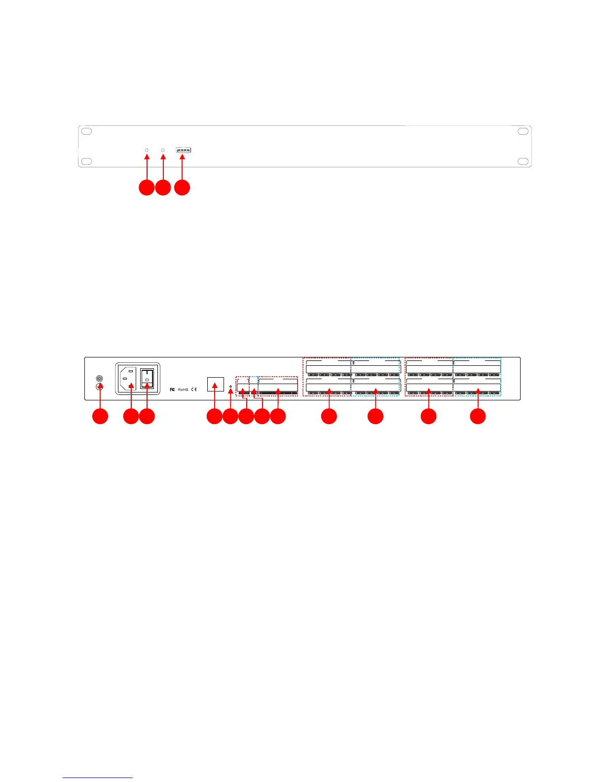
2.1 Front panel
(1)PWR: after the power supply is switched on, light indicates power status.
(2)SYS: the system will run normally if the indicator is flickering and the indicator will be off for a
long time during Starting.
(3)USB:the system supports USB recording.
2.2 Rear panel
(1)Chassis ground;
(2)Power plug, supporting AC 100V~240V power supply, 50~60Hz;
(3)Power switch;
(4)network interface, connect PC, on-line editing and command receiving and sending control;
(5)RESET: System reset button;
(6)RS232:communication interface, to connect the external central control equipment/ support camera
tracking;
(7)RS485:support camera tracking;
(8)GPIO:order transfer. For the specific connection mode, see GPIO setting in the 2.3 & appendix;
(9)OUTPUT:
Analog audio MIC \ LINE input interface;
(10)INPUT
: Analog audio output interface;