38 / 43
Appendix: GPIO
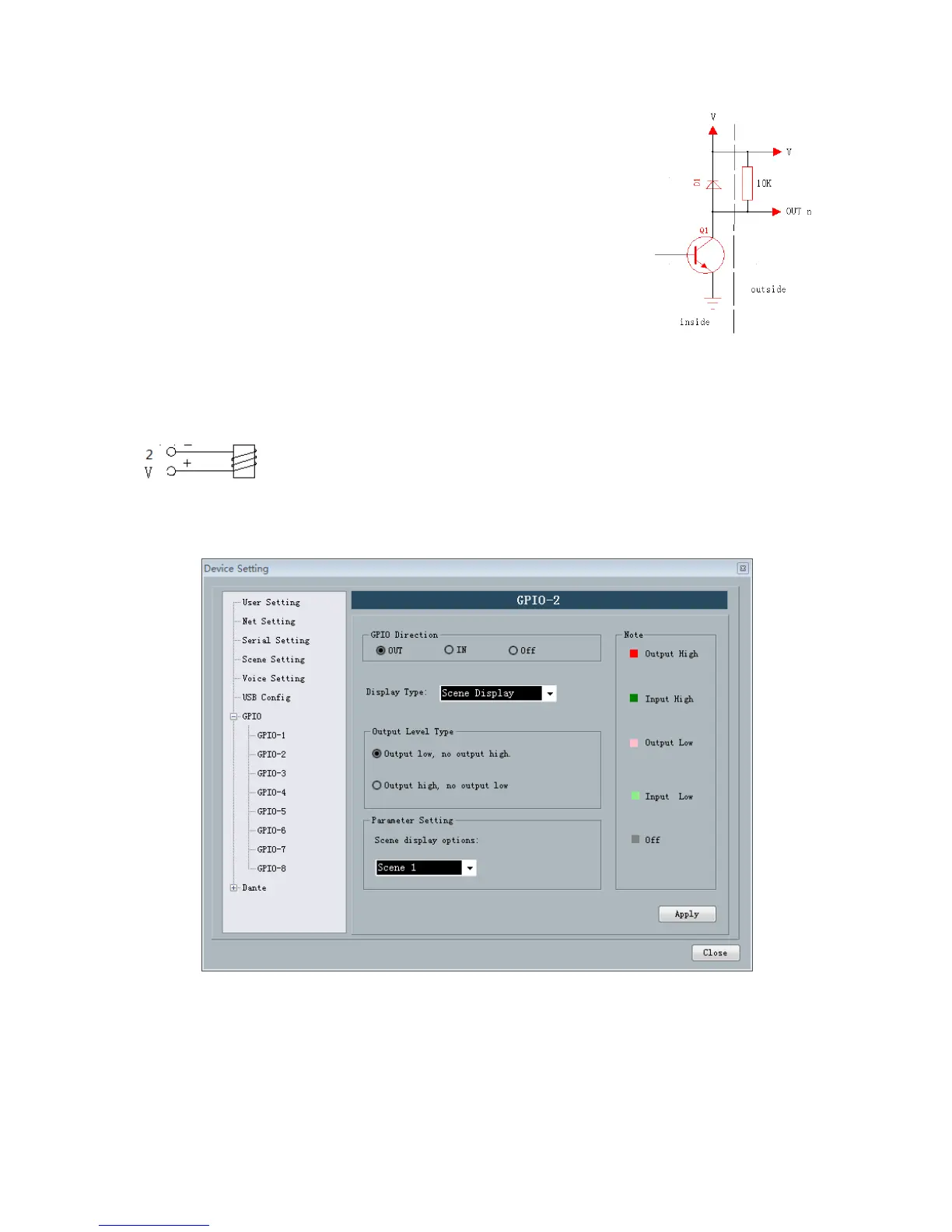
Output connection method 1: the first pin on the device in a
GPIO(such as port 2) resistance in a 10K/0.25W connection, this pin
according to the matrix of state change output low level 0 or 1 high level,
the level can be used to trigger another GPIO or other equipment.
Output connection method 2: Drive relay: relay can be used to control the alarm device,
built in the continued flow diode.
In accordance with the above method is also need to follow the following settings on the Software:
Settings ->Device settings ->Select GPIO channel (gpio-2 in this case) -> Set GPIO direction as "output":
a