NOTE
Record all faults on the Fault Record Sheet
supplied at the back of this manual.
ROUTINE MAINTENANCE
The Model 505 Transmitter requires no routine
maintenance, except for periodic checks to ensure
proper calibration. The frequency of these checks is
determined by the requirements of the particular
installation. Calibration gas kits are required for these
checks.
CHECKOUT IN NORMAL MODE
The entire gas detection system should be checked
periodically to ensure that the presence of gas at the
sensor will result in the proper system response.
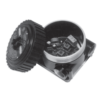
SENSOR INSPECTION
Since a dirty or plugged sensor filter can adversely
affect the response time of the sensor by restricting the
flow of gas to the sensing element, it should be
inspected on a regular basis. If a dust cover or splash
shield is used, it should also be checked.
SENSOR SENSITIVITY
If sensor response to 50% LFL methane is less than 15
millivolts, the sensor should be replaced. Refer to Table
2, “Calibration Procedure” for information regarding
calibration and sensor sensitivity.
SENSOR REPLACEMENT
De-classify the area prior to replacing the sensor and
secure any output devices connected to the system to
prevent unwanted actuation of this equipment. To
replace the sensor:
1. Verify that no hazardous levels of combustible gas
are present at the sensor, then remove the cover
from the junction box.
2. Unplug the sensor from the circuit board and
unscrew it from the junction box.
3. Coat the threads of the new sensor with silicone
free grease, then screw the sensor into the junction
box and plug it into the circuit board.
4. Allow the sensor output to stabilize under power
(about two hours minimum for best results), then
13 95-8472
SYMPTOM POSSIBLE CAUSE
Controller display shows full scale reading Over 100% LFL gas at sensor. Take appropriate safety measures.
Transmitter not calibrated.
Defective sensor.
Power (+) shorted to signal.
No output from transmitter. Power supply failure.
Power or signal wiring problem.
Negative % LFL display at controller. No power to transmitter.
Transmitter not calibrated.
Sensor not connected.
Defective sensor.
SIG wire problem.
CAL/NORM switch in CAL position.
Signal level at controller different than at transmitter. Loose wiring connection.
Total signal wiring loop impedence too high.
Induced EMI/RFI interference from nearby EMI fields (motors, switches, etc.).
Improper earth ground connection of signal wire shield.
Table 3—
Troubleshooting Guide