Conduit Seals, Drains, and Breathers
The Model 505 Transmitter is designed and approved
for use in hazardous areas where explosion-proof
equipment certification is required. When installing the
Model 505 in such areas, explosion-proof conduit seals
should be installed within 18 inches (46 cm) of the
transmitter housing. Conduit seals prevent the
passage of vapors or flames through the conduit. Seals
are recommended even if they are not required by local
wiring codes.
Conduit systems are never completely air-tight. As a
result, significant amounts of condensation can form
within the conduit system. Therefore, it is important to
take proper precautions during installation to ensure
that moisture will not cause damage to the transmitter or
other components of the system.
Conduit raceways should be inclined so that water will
flow to low points for drainage and will not collect on
conduit seals or inside enclosures. If this is not
possible, install conduit drains above the seals to
prevent the collection of water, or install a drain loop
below the detector with a conduit drain at the lowest
point of the loop.
Conduit drains should be installed at water collection
points to automatically drain accumulated moisture.
Conduit breathers should be installed at upper locations
to provide ventilation and allow water vapor to escape.
At least one breather should be used with each drain.
When using steel wire armored or mineral-insulated
copper-sheathed cable, select an approved gland with
a watertight compression stage and an overall gland
shroud for outdoor applications. A sealing washer must
be fitted between the gland and the conduit/cable entry
to ensure IP66 rating.
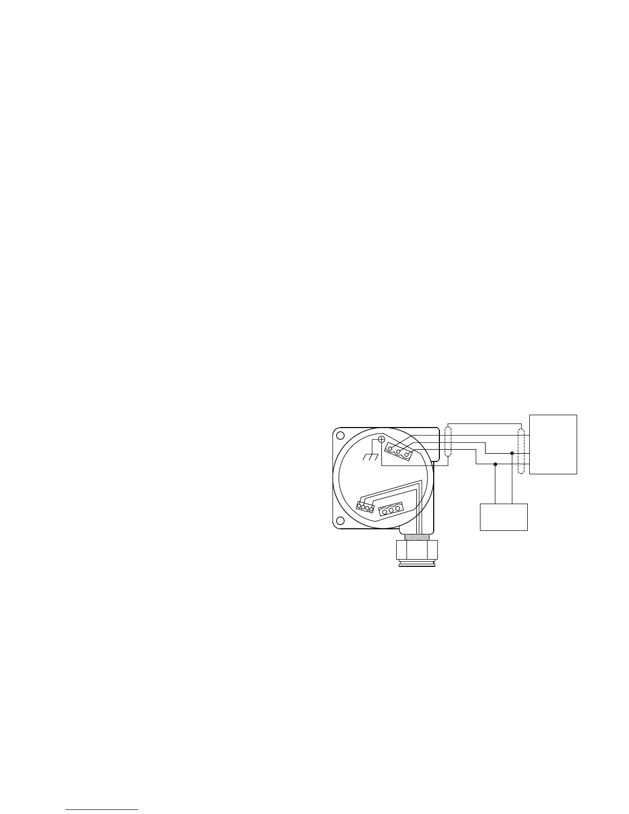
MODEL 505 WIRING
Wire the Model 505 as shown in Figure 1.
SENSOR SEPARATION
For maximum EMI/RFI protection, it is preferable to
mount the sensor directly to the Model 505 junction box.
However, in many cases it is desirable to locate the
sensor in a remote location where early gas detection is
most probable, and locate the transmitter in an easy-
access location. In this case, a Sensor Termination Box
(available from Detector Electronics) should be used to
install the sensor separately from the transmitter. See
Figure 2.
A continuous, three conductor cable with an overall foil
shield must be used with the sensor separation kit. The
cable shield drain wire should be cut back and
insulated within the sensor junction box and connected
to earth ground at the transmitter junction box. Failure
to use a shielded cable or properly ground the shield is
likely to result in nuisance alarms caused by EMI/RFI
problems.
The maximum separation distance between the sensor
and transmitter is limited by the electrical resistance of
the connecting wiring, which is a function of the gauge
of the wire being used. Table 1 gives the recommended
and absolute maximum sensor separation distances. If
the distance is less than the recommended maximum,
no adjustment to sensor voltage is required, although
measurement of the sensor voltage is recommended to
verify proper sensitivity. If the distance is greater than
the recommended maximum, refer to the “Sensor
Voltage Adjustment” section.
Sensor separation installations with the Model 505
require a special terminal plug for connecting the
sensor wiring to the transmitter. This connector (P/N
102883-001) is included with the Sensor Termination
Box, and is also available separately for existing
installations.
3 95-8472
1. DO NOT APPLY POWER TO THE TRANSMITTER WITH THE JUNCTION BOX COVER
REMOVED UNLESS THE AREA HAS BEEN DE-CLASSIFIED.
2. POSITION THE TRANSMITTER WITH THE SENSOR POINTING DOWN.
3. THE TRANSMITTER JUNCTION BOX SHOULD BE ELECTRICALLY CONNECTED TO
EARTH GROUND.
4. ATTACH THE SENSOR TO THE JUNCTION BOX TIGHTLY ENOUGH TO ENSURE AN
FUTURE REPLACEMENT. SILICONE BASED LUBRICANTS MUST NEVER BE USED.
5. CABLE SHIELDS SHOULD BE CONNECTED TO EARTH GROUND AT THE
TRANSMITTER END ONLY.
6. SHIELDS SHOULD BE STRIPPED BACK FROM CONDUCTORS ONLY WITHIN THE
JUNCTION BOX ENCLOSURE.