1. Use formula: C x K = S
C = Concentration of calibration gas in % LFL = 50
K = K-factor from Table 1 in GTN01 = 1.44
50 x 1.44 = 72
S = 72
2. Use formula: (S x 0.0067) + 0.17 = S1
S = span output level (determined in step 1) = 72
(72 x 0.0067) + 0.17 = S1
(72 x 0.0067) = 0.48
0.48 + 0.17 = 0.65
S1 = 0.65
3. Calibrate the Model 505 for a reading of 0.65 vdc
on the voltmeter with a calibration mixture of 50%
LFL methane applied to the sensor.
NOTE
This procedure applies only to the Model 505
Transmitter. Other Det-Tronics transmitters use
the standard K-factor formula as described in
GTN01.
7 95-8472
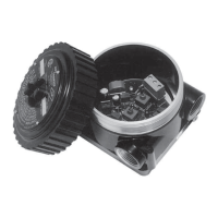
WARNING
Before removing the junction box cover, verify that no dangerous levels of gas are present.
Step Switch Position Operator Action
1 CAL/NORM switch in the CAL position. 1. LED turns on.
2. Connect a digital voltmeter to the transmitter test jacks.
3. Set the meter range to 2 vdc.
2 ZERO/SPAN switch in the ZERO position. 1. Adjust the ZERO potentiometer to read 0.000 vdc on the voltmeter.
See Note 3 below.
3 ZERO/SPAN switch in the SPAN position. 1. Adjust the 4 ma potentiometer to read 0.167 vdc on the voltmeter.
2. Apply the 50% LFL calibration gas to the sensor. When the output has
stabilized, adjust the SPAN potentiometer for a reading of 0.500 on the
voltmeter.
4 ZERO/SPAN switch in the ZERO position. 1. Sensitivity test. The meter must read greater than 0.015 vdc. See Note
4 below.
2. Remove the calibration gas.
3. When the meter reads 0.002 vdc or less, remove the test probes.
5 CAL/NORM switch in NORM position. 1. The LED turns off.
2. The calibration is complete.
3. Replace the junction box cover.
NOTES:
1. When the CAL/NORM switch is in the CAL position, the yellow LED turns on and the 4 to 20 ma output signal goes to 3.4 ma.
2. The voltmeter must be suitable for use in a hazardous location.
3. If the possibility of background gases exists, purge the sensor with clean air prior to the zero adjustment to assure accurate
calibration.
4. A typical sensitivity reading with 50% LFL gas applied to the sensor is 35 to 50 millivolts for a new sensor. Sensor
replacement is recommended when the sensitivity reading is less than 15 millivolts.
5. If a dust cover or splash shield is used, inspect it to be sure that it is not dirty or plugged. A plugged dust cover can restrict the
flow of gas to the sensing element, seriously reducing its effectiveness. For optimum performance, sensor covers/filters
should be replaced frequently to ensure that they are not degraded or plugged.
Table 2—
Calibration Procedure