G-1 95-852613.1
Appendix G
MODBUS COMMUNICATION
OVERVIEW
This appendix outlines the communication protocol and related memory structures that define the interface between
PointWatch Eclipse Gas Detector and a system MODBUS Master. The system MODBUS Master is defined as any
device capable of reading and writing to the holding register area of a MODBUS slave device. This includes proprietary
software, HMI systems such as Wonderware and The FIX, PLCs and DCSs.
The Eclipse will respond as a slave device to a MODBUS Master, allowing the master to control data flow. A MODBUS
memorymapisdened,whichdividesmemoryintofunctionalblocksconsistingof:factoryconstants,conguration
information,realtimestatus,controlanddevicedenedinformation.Eachblockisthensubdividedintoindividual
variables that may be simple integers or floating point numbers.
WIRING
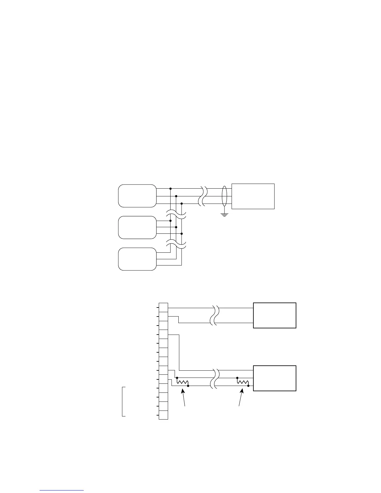
Typical RS-485/Modbus communication architecture is indicated in the diagram below. Eclipse units act as slave
devices to a Modbus Master. Multiple Eclipse units are daisy-chained for RS-485 communication. If long cable runs
are used, 120 Ohm end-of-line termination resistors may be required.
Individual Eclipse units are wired as shown below. Note the inclusion of the end-of-line termination resistor.
For more information, refer to the EIA RS-485-A standard.
A2341
–24 VDC
–24 VDC
+24 VDC
+24 VDC
CALIBRATE
+ 4-20 MA
– 4-20 MA
RS-485 A
RS-485 B
RELAY POWER
FAULT
LOW ALARM
HIGH ALARM
NO USER CONNECTION
1
2
3
4
5
6
7
8
9
10
11
12
13
24 VDC
POWER SUPPLY
+
–
MODBUS
MASTER
GND
A
B
PIRECL
120 OHM TERMINATION RESISTOR
ON MASTER AND LAST SLAVE IN DAISY CHAIN
A2340
MODBUS
MASTER
GND
A
B
ECLIPSE
SLAVE #1
ECLIPSE
SLAVE #2
ECLIPSE
SLAVE #N