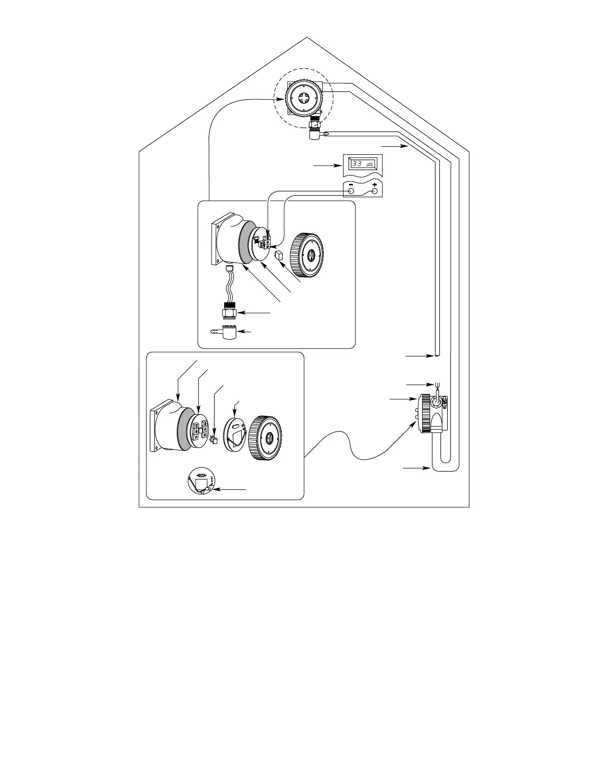
SENSOR/TRANSMITTER WIRING (without Sensor
Separation)
The following section describes the installation and
wiring procedure for K Series Transmitters. When
using other transmitter models, mount and wire the
sensor and transmitter as described in the transmitter
manual.
1. Locate the sensors in positions that are best suit-
ed for covering the area to be protected, following
the previously discussed guidelines. Whenever
practical, they should be placed where they are
easily accessible for calibration.
NOTE
Do not apply power to the system with the junc-
tion box cover removed unless the area has
been de-classified.
2. Remove the cover from the transmitter junction
box.
NOTE
The transmitter and controller contain semicon-
ductor devices that are susceptible to damage by
electrostatic discharge. An electrostatic charge
can build up on the skin and discharge when an
object is touched. Therefore, use caution when
11 95-8398
Figure 5—Sensor Separation with K Series Transmitter


 To Next Page