SYSTEM OPERATION
SENSOR
Det-Tronics combustible gas sensors use a catalytic
type sensing element and operate in the range of 0 to
100% LFL. Sensors are available in aluminum or
stainless steel housings, with a choice of three sens-
ing elements - standard, poison resistant, and high
temperature. With proper calibration, the sensor can
be used to detect a wide variety of combustible
gases. Contact Detector Electronics for assistance in
adapting the sensor to a specific application.
TRANSMITTER
The transmitter functions as the interface between the
sensor and the controller. It regulates operating
power to the sensor and generates a linear 4 to 20 ma
output signal proportional to 0 to 100% LFL com-
bustible gas concentration.
A transmitter output signal of less than 4 ma is dis-
played as a negative reading by the controller.
The sensor is normally threaded directly to the trans-
mitter enclosure. However, the sensor and transmitter
can be mounted separately using a Sensor
Separation Kit available from Detector Electronics.
The sensor, transmitter and separation kit are
designed for use in hazardous areas, and when prop-
erly installed will provide an explosion-proof installa-
tion.
Detector Electronics offers a variety of transmitter
models that operate in the 0 to 100% LFL range and
are compatible with the R8471 Controller. Refer to
the “Ordering Information” section for more informa-
tion.
CONTROLLER
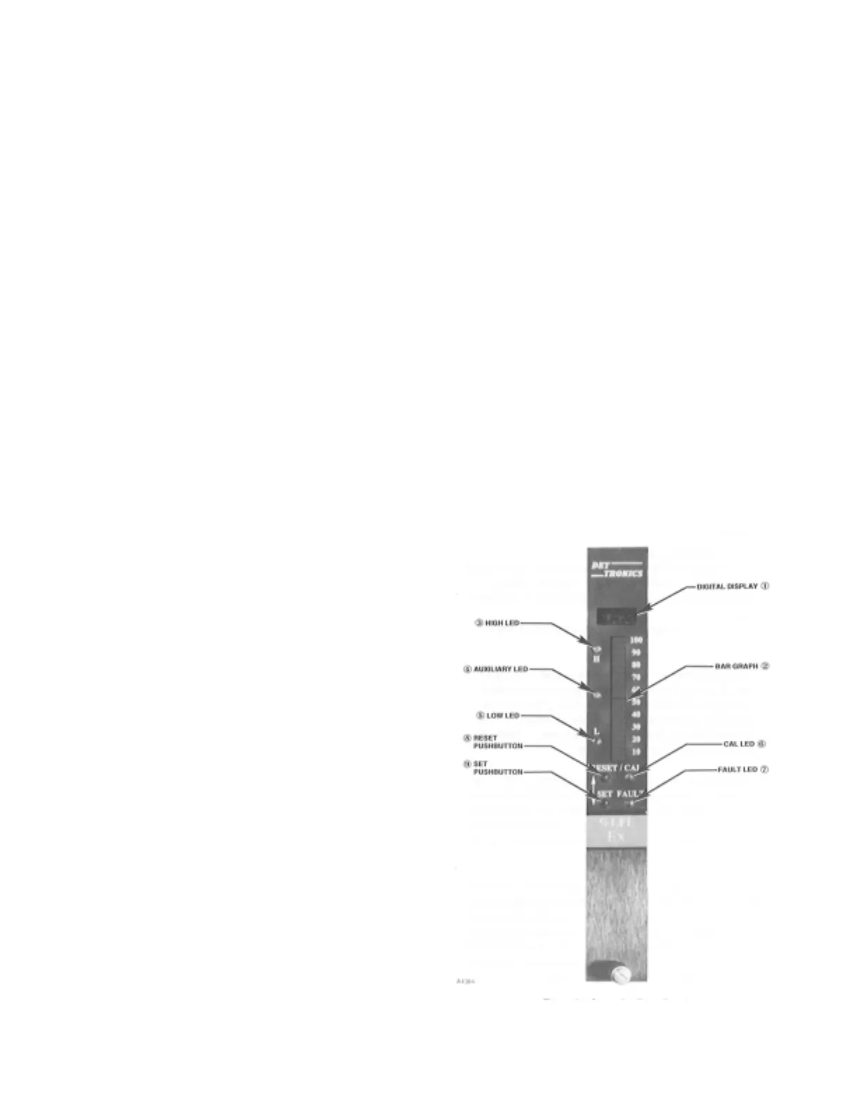
Faceplate Description
The faceplate of the controller provides LEDs for iden-
tifying status conditions, a digital display and bar
graph display for indicating the sensor input, and
pushbuttons for programming, calibrating and reset-
ting the system. See Figure 2 for the location of indi-
cators and pushbuttons.
1. Digital Display—The digital display continuously
provides a % LFL reading of the sensor input in
both the Normal and Calibrate modes. In the
event of a fault, it identifies the nature of the fault
using an alpha-numeric code. In other operating
modes it shows the alarm setpoints and pro-
grammed calibration gas concentration. A nega-
tive zero drift condition is indicated by a minus (–)
sign in the left hand digit. If an over-range condi-
tion occurs, the display flashes and the highest
reading latches on. Since this display is always
on, it also functions as a power indicator.
2. Bar Graph Display—The 20 segment bar graph
display provides a reading of sensor input in 5%
LFL increments.
3. High Alarm LED—Flashes in response to a sensor
signal that exceeds the high setpoint.
4. Auxiliary Alarm LED—Flashes in response to a
sensor signal that exceeds the auxiliary setpoint.
5. Low Alarm LED—Flashes in response to a sensor
signal that exceeds the low setpoint.
NOTE
The alarm LEDs flash when the setpoint is
exceeded and are on steady (until reset) when
the gas level drops below the setpoint, whether
the corresponding alarm output is latching or
non-latching.
3 95-8398
Figure 2—Controller Front Panel