NOTE
The fault code will be shown for about 2 seconds
out of every 5 seconds. The gas concentration
at the sensor will be displayed during the remain-
ing time. If more than one fault should occur, the
highest priority fault will be displayed. (Table 2
lists the faults in order of priority.)
An alarm condition will normally over-ride a fault con-
dition unless the fault condition occurred first (except
F10, F2X). However, faults that affect the actual func-
tion of the controller (F50, F60, F70, F9X) can impair
the ability of the controller to maintain an alarm out-
put.
All faults automatically reset except the F9X, F20, and
F10 faults. After the fault condition has been correct-
ed, the fault output automatically switches to the nor-
mal (energized) state, the dc current output returns to
normal, and the Fault LED turns off. Clearing F9X
faults requires removing operating power from the
controller for approximately one second.
CAUTION
The fault detection circuitry does not monitor the
operation of external response equipment or the
external wiring to these devices. It is important
that these devices be checked periodically to
ensure that they are operational.
Operating Modes
NOTE
The following section is intended to acquaint the
operator with the basic operation of the con-
troller. For complete step-by-step programming
and calibration procedures, refer to the corre-
sponding sections in this manual.
The controller can operate in any of the following
modes. Operating modes other than Normal are
selected by pressing the appropriate pushbutton(s)
located on the controller front panel. See Figure 3.
NORMAL
In the Normal operating mode with no alarm condi-
tion:
— Digital display is on and indicates the sensor input
in % LFL.
— Bar graph display reads the same as the digital
display.
— All LEDs are off.
— Alarm outputs are in their normal state (energized
or de-energized as programmed).
— DC current output signal level corresponds to sen-
sor input.
— Fault output is energized.
In the Normal operating mode with a low and/or auxil-
iary alarm condition occurring:
— Digital display and bar graph display indicate the
sensor input in % LFL.
— Low and/or Auxiliary LED flashes.
5 95-8398
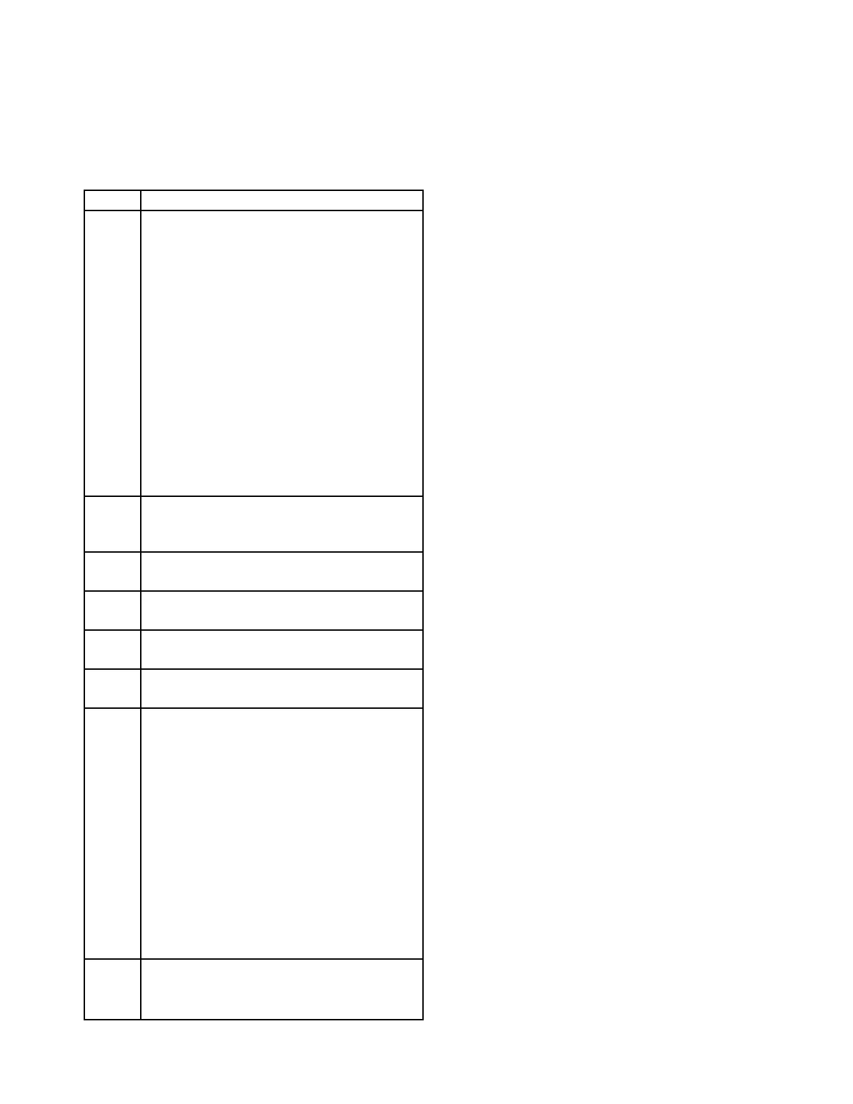
Table 2—System Status Codes
Status Condition
F9X Initialization failure. (Subcodes are as fol-
lows.)
F91 EPROM sumcheck failure.
F92 Sensor failure during startup - current too
high or too low.
F93 Watchdog timer failure.
F94 RAM failure.
F95 Internal 5 volt power supply failure during
startup.
F96 External 24 volt power supply failure dur-
ing startup.
F97 Controller type invalid. Error in data from
RAM.
F98 Watchdog timer reset the controller.
F70 External reset button has been activated
for 15 seconds or longer. Self clearing
when button is released.
F60 External 24 vdc power input is not in the
18 to 32 vdc range.
F50 Internal 5 volt power supply is not in the
4.75 to 5.25 volt range.
F40 Sensor fault (after startup). Input is above
35 ma or below 2 ma.
F30 Negative zero drift. Sensor input is –9%
full scale or lower.
F2X Calibration error. (Subcodes are as fol-
lows.)
F20 General calibration fault, or calibration
aborted due to a higher priority fault.
F21 Time ran out while waiting for calibration
gas to be applied to the sensor.
F22 Sensor input is too low. The sensor cannot
generate enough offset to get an accurate
calibration. Replace sensor.
F23 Sensor is too sensitive for the controller to
read 100% full scale. Replace sensor.
F24 Zero gas level too high, or sensor zero
input over limit.
F10 Sensor reaching end of life. Consider
replacing the sensor within the next two
calibration periods.