— Low and/or Auxiliary alarm output changes state.
— Dc current output signal level corresponds to sen-
sor input.
— Fault output energized and LED off.
When the signal decreases below the low or auxiliary
setpoint:
— Digital display, bar graph display, and 4 to 20 ma
output continue to track the sensor input.
— With latching operation programmed: No change
to alarm outputs.
— With non-latching operation programmed: Alarm
outputs return to their normal state.
— Low and Auxiliary LEDs are on steady until reset.
In the Normal operating mode and a high alarm con-
dition occurring:
— Same as low or auxiliary alarm, but High LED is on
and high alarm output is actuated.
When the signal decreases below the high alarm set-
point:
— The high alarm is always latching and unaffected
by the latching/non-latching programming for the
low and auxiliary alarms. High LED is on steady
until reset.
In the event of a system fault:
— The normally energized Fault output is de-ener-
gized and the Fault LED is illuminated.
RESET
The Reset mode is the first mode that is entered by
pressing the Reset button located on the front panel
of the controller. (See Figure 3.) When the Reset but-
ton is momentarily depressed, all LEDs turn off and
all outputs return to their normal condition if no alarms
or faults are occurring (basic reset). When the Reset
button is held for 0.5 second, the LEDs turn off and
the outputs return to their normal condition even if an
alarm or fault condition still exists (forced reset).
Remote reset capability is also provided. (Remote
reset performs a forced reset.)
NOTE
The remote reset performs a reset function
only. It cannot be used for entering other
controller operating modes.
SETPOINT DISPLAY MODE
If the Reset button is held for approximately one sec-
ond, the digital display sequentially shows the pro-
grammed alarm setpoints and calibration gas con-
6
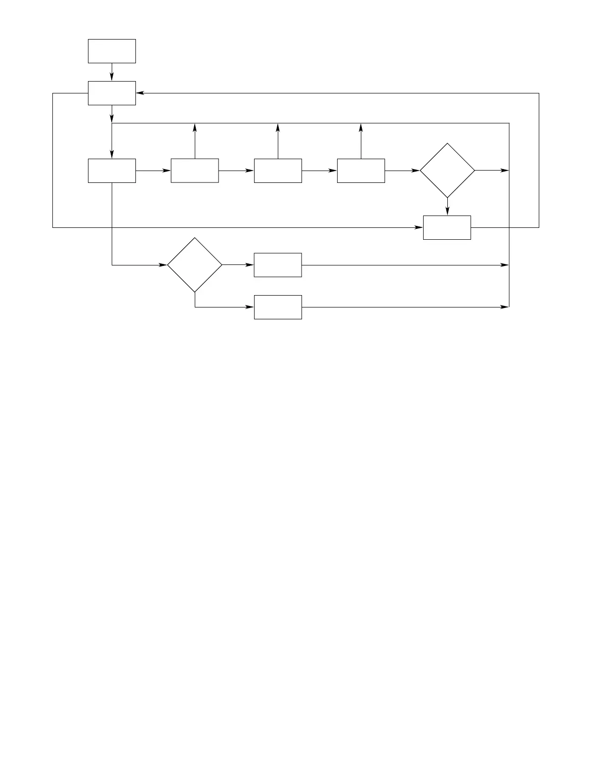
Figure 3—R8471 Controller Flow Chart