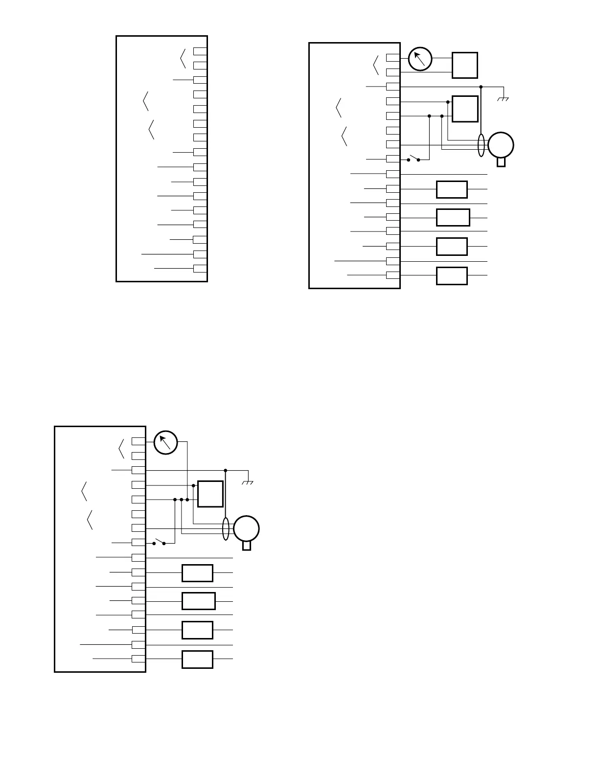
section. Note that this wiring scheme requires an
external power source for the isolated current out-
put.
Terminal 3— Chassis ground. Ground the cable
shield at this terminal.
NOTE
If local wiring codes permit and if a ground fault
monitoring system is not being used, the minus
side of the dc power source can be connected to
chassis (earth) ground. Alternatively, a 0.47
microfarad, 100 volt capacitor can be installed
(terminal 5 to ground) for best immunity against
electromagnetic interference.
Terminal 4— Connect to the positive (+) side of the
18 to 32 vdc power source.
Terminal 5— Connect to the negative (–) side of the
dc power source.
Terminal 6— Make no connections to this terminal.
Terminal 7— 4 to 20 ma dc signal input from transmit-
ter/sensor assembly.
Terminal 8— A normally open momentary closure
switch can be connected between this
terminal and the negative (–) side of the
power source for remote reset.
Terminals 9 and 10— High Alarm Output.
Terminals 11 and 12— Auxiliary Alarm Output.
Terminals 13 and 14— Low Alarm Output.
Terminals 15 and 16— Fault Output.
14
Figure 10—A Typical System with Relay Outputs and Non-Isolated
Current Output


 To Next Page