Do you have a question about the Detroit Diesel Series 60 EGR and is the answer not in the manual?
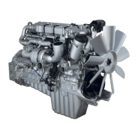
| Cooling System | Liquid-cooled |
|---|---|
| Engine Type | Diesel |
| Configuration | Inline-6 |
| Aspiration | Turbocharged |
| Bore | 130 mm |
| Stroke | 160 mm |
| Torque | 1250 lb-ft |
| Fuel System | Electronic Unit Injector (EUI) |
| Emissions Compliance | EPA |
| Displacement | 12.7 L |
Essential checks to perform before starting any troubleshooting procedure for the engine and its systems.
Guidelines for technicians to gather information from the operator regarding intermittent problems and symptoms.
Description of the ECM as the backbone for engine management, receiving sensor inputs for operation.
Details the VPOD's role in controlling EGR valve and VNT actuator via modulated air pressure.
Explains the VNT's function using a pneumatic actuator to regulate turbine vanes for boost and EGR control.
Describes the EGR valve's position control by the ECM and its function in recirculating exhaust gases.
Explains the EGR cooler's purpose: to cool exhaust gases before they enter the intake manifold.
Details the Delta P Sensor's function in monitoring pressure differential for EGR flow rate determination.
Engine operation mode where no EGR is flowing and turbocharger vanes adjust for boost.
Engine operation mode where EGR is flowing at a desired rate for emission control.
Engine mode in cold conditions where EGR is disabled to prevent condensation.
Lists and describes various DDEC IV diagnostic trouble codes (DTCs) for system analysis.
Details specific sensor failures and the system's response to these faults.
Codes indicating conditions that could cause engine damage, triggering engine protection.
Procedure for testing the Charge Air Cooler (CAC) system integrity and EGR valve operation.
Procedure for testing VNT and EGR valve rod travel using dynamometer or engine operation.
Troubleshooting steps for diagnosing intermittent black smoke issues in the engine.
Troubleshooting steps for addressing engine power loss during heavy load conditions.
Procedure to test the output pressure from the VPOD for proper EGR and VNT valve actuation.
Steps to read and record active diagnostic trouble codes (DTCs) using DDDL or DDR.
Guide on how to initiate and record a snapshot of engine parameters using DDDL.
Instructions for opening, replaying, and analyzing recorded DDDL snapshot data.
Illustrates normal engine operation parameters and smooth transitions in DDDL snapshots.
Provides tips for troubleshooting EGR flow issues based on Delta P sensor readings.
Graphical illustration and primary purpose of the DDEC V EGR system for emission reduction.
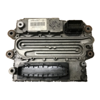
Details the location and function of the DDEC V ECU in engine management and diagnostics.
Details the functions of specific EGR components within the DDEC V system.
Describes the hydraulically actuated EGR valve and its operation via ECU PWM signal.
Explains the EGR cooler's role in cooling exhaust gases for intake manifold entry.
Details the Delta P Sensor's function in determining EGR flow rate based on pressure differential.
Explains logic codes indicating mechanical failures detected by the DDEC V system.
Troubleshooting steps for Flash Code 13: EGR valve electric current too high.
Details failure modes for EGR valve electric current being too low (FMI 5) or too high (FMI 6).
Recommendations for troubleshooting specific operational concerns and probable complaints.
Troubleshooting steps for addressing issues causing black smoke from the engine exhaust.
Troubleshooting steps for diagnosing and resolving poor engine performance issues.
Troubleshooting steps for identifying and resolving engine coolant loss issues.
Procedure to check the Delta P Sensor for proper operation and data counts.
Procedure to test the VPOD's output pressure for correct operation of actuators.
Procedure to test the wiring harness connections for the VPOD.
Procedure to verify that all repairs have resolved the original complaint and codes.
Diagram showing the front side view of the DDEC IV ECM and its connectors.
Diagram illustrating the ECM engine harness connector and its pin layout.
Table detailing pin locations, wire numbers, and colors for the engine harness connector.
Diagram showing the vehicle interface harness connector and its pin configuration.