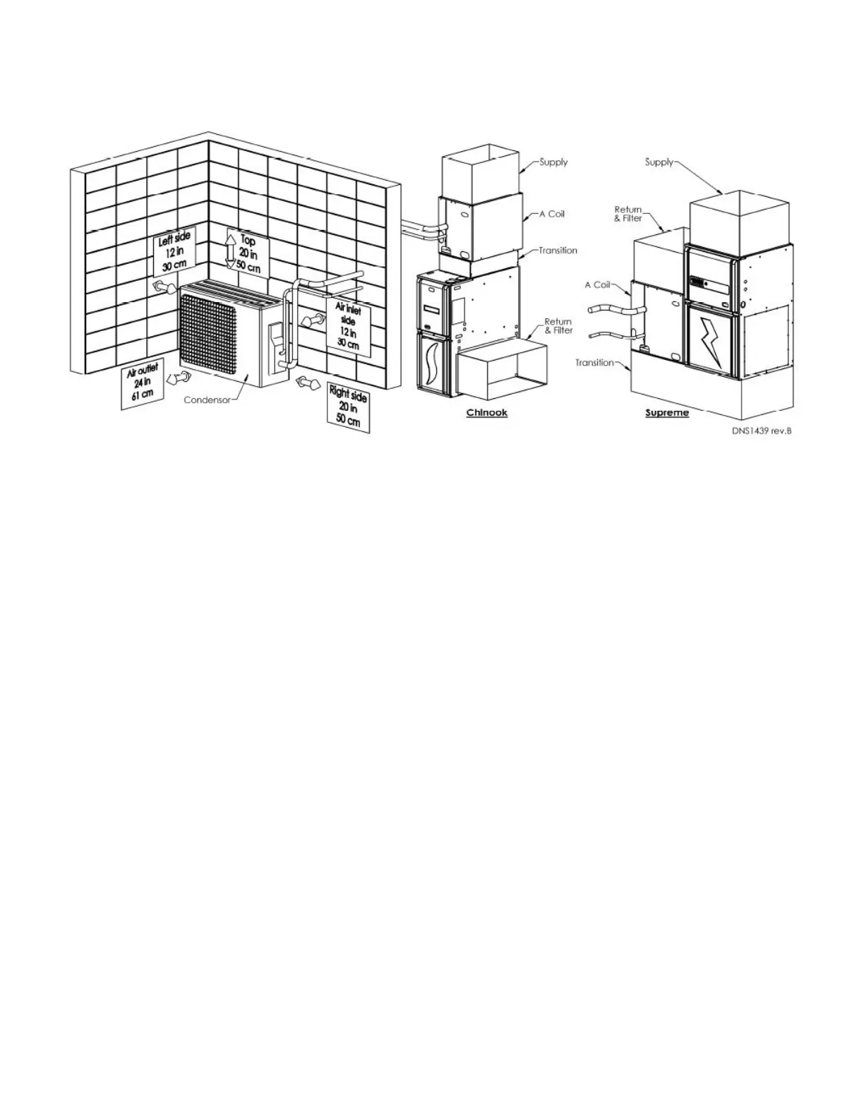
3.4 Clearances
Figure 1 – Installation and Clearances
3.5 Indoor Coil
Check the coil for shipping damage and verify the
contents of the box containing the evaporator coil. If you
should find damage, immediately contact the last carrier.
Coils are shipped with a 10 psi dry air holding charge.
Puncture rubber plug on suction line to release charge
before removing plugs. The absence of pressure does
not verify a leak. Check the coil for leaks before installing
or returning it to your wholesaler.
Coil should be level, or pitched slightly toward the drain
connection. Airflow face velocity above 350 ft/min is not
recommended for downflow or counterflow applications
due to potential water blow-off.
For an installation with a Chinook, position the coil on the
supply outlet of the furnace using sheet metal screws.
Drain pans are made of a polymer that can withstand
temperatures up to 232°C (450°F). Maintain a minimum
of 3” clearance over the heat exchanger.
For an installation with a Supreme, position the coil on
the return outlet of the furnace.
A splashguard is included for horizontal installations
(multiposition colis). In downflow and counter flow
configurations, aluminum foil tape must be applied to seal
the top edge of the insulation to the cabinet.
Do not install any metering device on the indoor coil.
The expension valve is located in the outdoor unit.
If a metering device is already installed in the indoor
coil, it must be removed.
Condensate Drain
Coils are equipped with multiple drain connections.
Determine the drain connections to be used and note the
difference between the primary (green) and secondary
(red) openings. Drain plugs are provided for all openings;
remove and discard the appropriate plugs with ½” drive
ratchet and verify that remaining plugs are tight (2.5 ft-
lbs). Attach drain line to pan with ¾” male pipe thread
PVC fittings. Hand tight is adequate – do not over
tighten and do not reduce drain line size.
Route drain line(s) line so they will not be exposed
to freezing temperatures and do not interfere with
accessibility to the coil, air handling system or filter. The
drain should be pitched downward 1” per 10’ with a 2”
trap as close to the coil as possible. If line makes a
second trap, or has an extended run before termination,
a vent tee should be installed after the trap closest to the
pan.
If the coil is located in or above a living space where
damage may occur from condensate overflow, a separate
¾” drain must be provided from the secondary drain
connection. Run this drain to a place in compliance with
local installation codes where it will be noticed when unit
is operational. Condensate flowing from the secondary
drain indicates a plugged primary drain. Prime the trap
with water. Test line for leaks. Test water flow with unit in
operation. An auxiliary drain pan should also be installed
under the unit as specified by most local building codes.
3.6 Interface Board (K03081)
Installation of the interface card is made easy on the
Dettson’s Chinook and Supreme furnaces. Installation
port has been designed on these furnaces. Refer to the
installation instructions provided with the interface board
6


 To Next Page