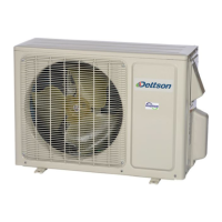
for installation location and thermostat wiring. Wire to the
outdoor unit as shown in the figure.
Figure 2 – Winting Interface Board to ODU
Communication wire connected between the indoor
and outdoor units must be rated for at least 120VAC,
they are protected by the outdoor unit breaker and
must be sized appropriatly.
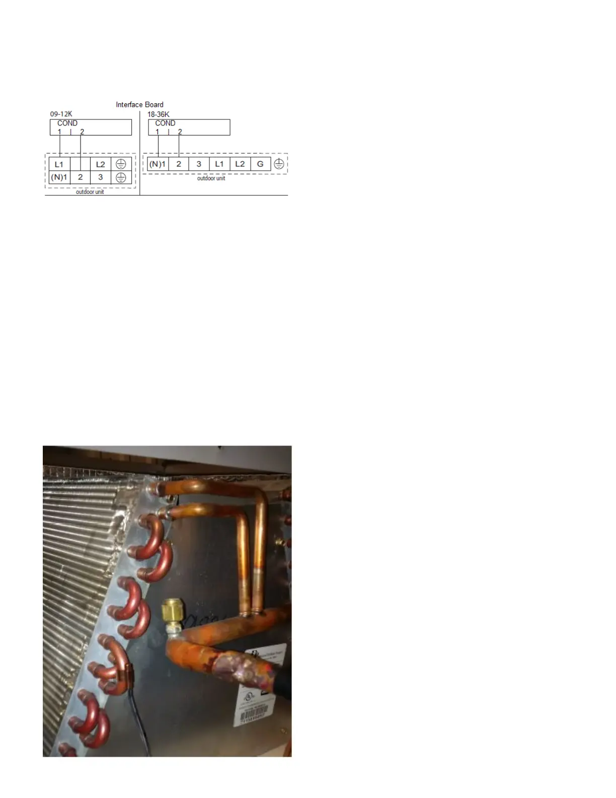
Coil Sensor
With the interface board kit comes a coil sensor. It must
be properly installed.
1. Attach the provided temperature sensor to the
evaporator coil as shown;
2. Get the wire through the refrigerant line opening;
3. Cut the wire and skin the conductors. Add wire
length if necessary;
4. Connect the two conductors to T1 and TC on the
interface card. The polarity is not important.
Figure 3 – Indoor Coil Sensor Location
3.7 Outdoor Unit
Electrical Wiring
1. Remove the handle on the right side plate of
outdoor unit;
2. Remove cord anchor. Connect and fasten power
connection cord to the terminal board;
3. Secure the power connection cord cord anchor;
4. Make sure the wires have been fastened properly.
NOTE: Incorrect wiring may cause malfunction.
L1 and L2 must be connected to the 208/230VAC power
supply. The unit must be properly grounded via the
ground terminal.
After the wires have been fastened, ensure there is free
space between the connection and fastening places on
the main wire.
Air Purging and Leakage Test
1. Connect charging hose of manifold valve to charge
end of low pressure valve (both high/low must be
tightly shut);
2. Connect joint of charging hose to vacuum pump;
3. Fully open the handle of Lo manifold valve;
4. Open the vacuum pump for vacuumization. At the
beginning, slightly loosen joint nut of low pressure
valve to check if there is air entering. Then, tighten
the nut;
5. Keep evacuating for more than 15 min. and make
sure the reading of multi-meter is -100 kPa(-76
cmHg);
6. Fully open high/low pressure valves;
7. Remove charging hose from charging end of low
pressure valve;
8. Tighten bonnet of low pressure valve.
Condensate Drainage
During heating operation, the condensate and defrosting
water should be drained through the drain hose. Install
the outdoor drain connector in a φ 0.98 in hole on the
base plate, and attach the drain hose to the connector so
that the waste water formed in the outdoor unit can be
drained. The hole φ 0.98 in must be plugged. Whether
to plug other holes or not will be determined by the
technician.
7
 Loading...