Before proceeding with the connec!ons, carefully read the sec!ons related to SAFETY. All wiring
and connec!on opera!ons must be performed with the control board disconnected.
Power supply; if the disconnec!on device is not visible, post a warning plate: “ATTENTION:
MAINTENANCE IN PROGRESS”.
The internal wiring of the electromechanical actuator that has been made by the company must
not be modified.
2.7 - Inser!on of electric cables in the gearmotor
ATTENTION: the cables used must be suitable for the type of installa!on; this evalua!on is the
responsibility of the installer.
• The power cord must not be lighter than 60245 IEC 57 (HO5RN-F).
• Inside the power cord, one wire must be yellow and green for grounding.
• The coa!ng of the power cable must consist of a polychloroprene sheath.
• All cables must be stripped to the minimum necessary, maximum 6 mm, as close as possible
to the connec!on terminals, to avoid accidental contact with live parts if the cable comes off
from the terminal.
• Do not pre-!n the cables that are to be screwed to the terminals.
• Use the power cord fastener.
a) Remove the cover from the gearmotor.
b) Open the holes provided in the cable gland membrane, then insert the cables necessary for
the connec!ons (keep the 230V cables separate from those at very low voltage).
Leave the cables approximately 40 cm longer.
c) Insert and make sure that the cable membrane is well adherent to the base of the gearmotor
to prevent access to insects and dirt.
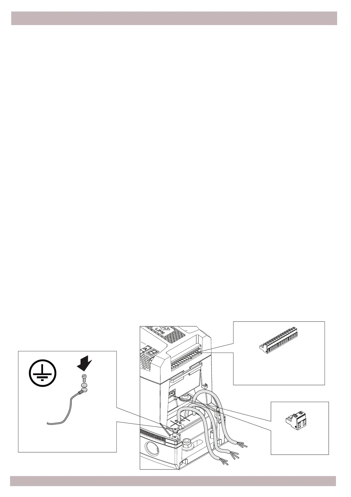
For safety reasons it is mandatory to connect the motor grounding.
Crimp the yellow-green wire of the power cable into the eyelet placed in the aluminum base.
2.6 - Wiring and connec!ons
Yellow-Green Cable
Accessory connec!on
Low voltage
Power
230Vac 50Hz