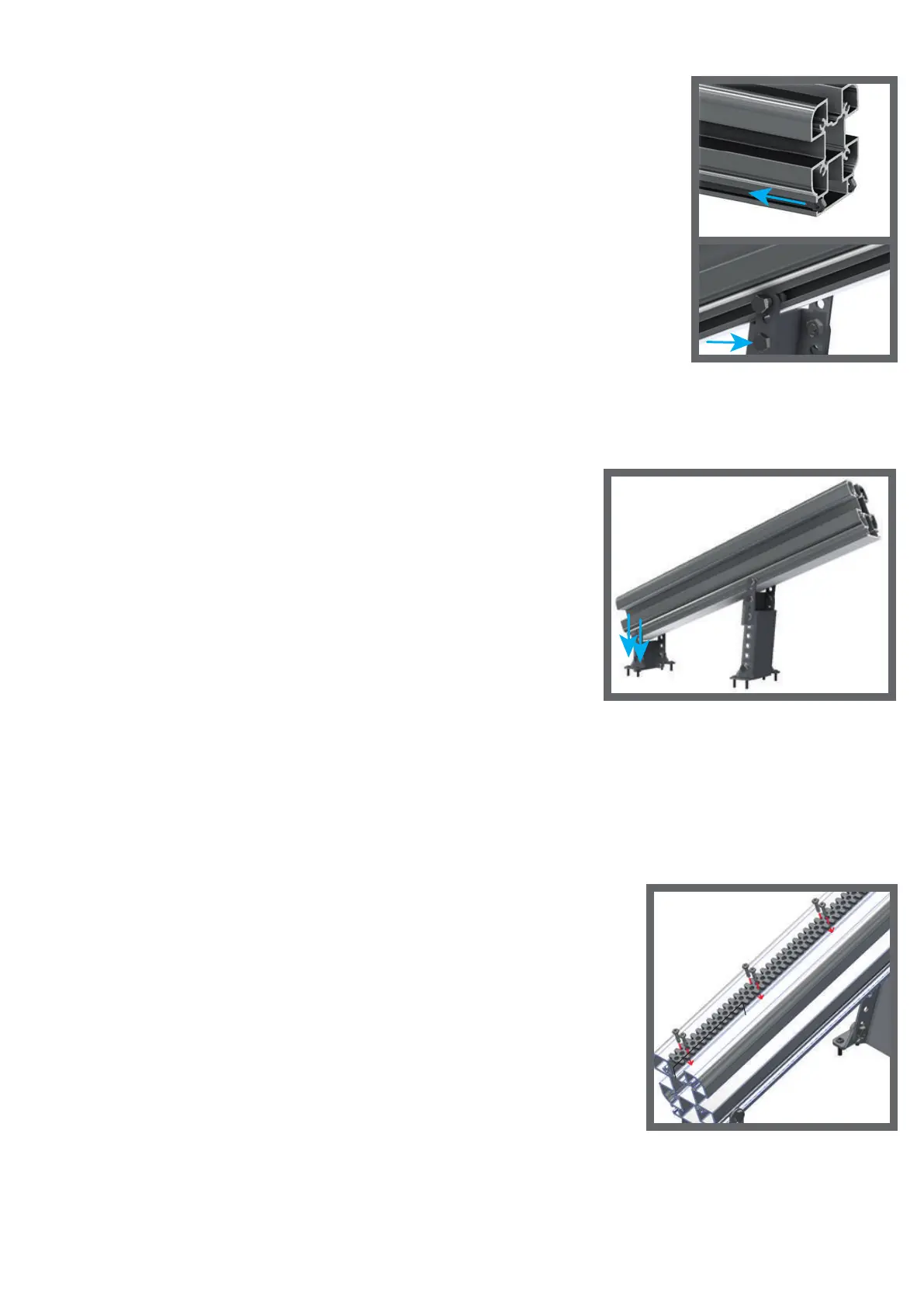
3. Slide a nut M8 ISO 4017 in both of the two slots pointed
out by the blue arrow in figure 11.
4. Fix the mounts by a bolt M8x16 DIN 934 through the last
hole of a mount and the nuts M8 ISO 4017 placed in step 3.
See figure 12, for the holes to put the bolts through.
Make sure that the triangular mounts can be placed entirely
and securely on the ground or a step of the stairs. Do not fix
the bolt entirely until this is achieved.
5. When a good location for the rail support is found,
fully fix the bolt from step 4. Besides, fix the rail
support short to the floor or the step of the stairs.
Drill first a hole in the stairs with drill 4 or 3.5.
Then use four screws 6x30MM through the
holes pointed out in figure 13.
6. Place rail supports close before and close after each turn. For the straight
parts place rail supports approximately every meter. However, do not place
the rail supports at the two ends of the rail yet, this would block the access
for the charging station.
7. When the rail is mounted, the gear rack can be put in.
The rail can be fixed with ST3.9x16 DIN 7504 screws
in the outer gaps. They are pointed out in figure 14.
Always make sure that the screws are placed as far as
possible against the side of the slot. Start with the gear
rack 5 cm from the beginning of the rail so that it is
easier to place the carriage on the rail.
Do not place screws in the holes in the middle, these
are for the pinion to drive. When there is a curve, the
rack can be bent with a bending tool to get the
right shape for the turn. Place the screws every
10 cm and before and after every curve.
12
(fig. 11)
(fig. 12)
(fig. 13)
(fig. 14)
1
0
0
m
m
 Loading...