AT commands: Detailed description
|
|
devolo MicroLink ISDN i
|
54
EN
3.3.1 V.24 interface
The interface between the MicroLink ISDN i and the computer consists of a
variety of data, control and signaling lines. The condition of most of the inter
-
face lines is displayed by LEDs on the front of the unit.
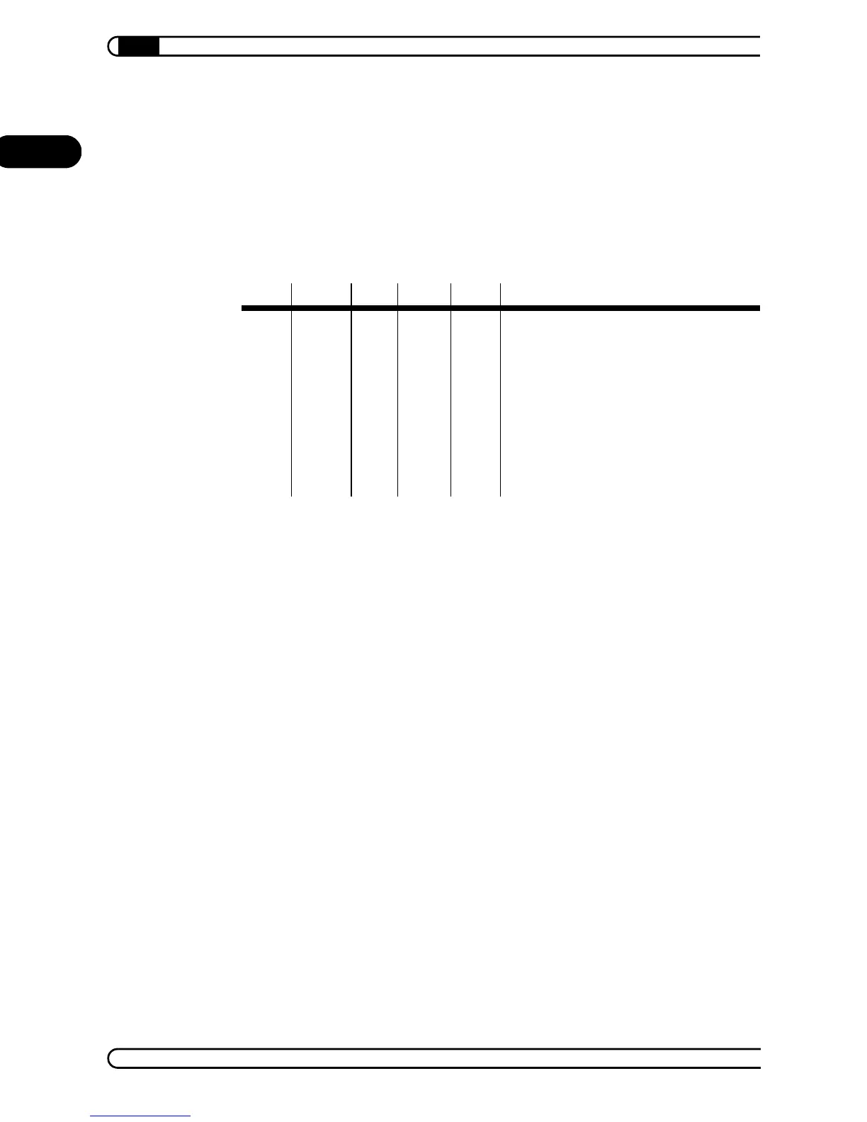
The pin assignment of the V.24 interface for 9-pin or 25-pin connectors is as
follows:
* U = Housing/shield
The designations in the table name the functions of the lines (e.g. transmis-
sion data) as related to the data terminal (computer).
3.3.2 The interface lines have the following significance:
Computer/terminal operational – DTR = Data Terminal Ready
The effect of this control line on the MicroLink ISDN i is determined by the
command AT&D.
Switch on transmission – RTS = Request To Send
Operational – DSR = Data Set Ready
This signal line is normally always active (ON), but is influenced by the com-
mands AT\D and AT&S.
Clear to send – CTS = Clear To Send
This output is normally always active (ON), but is influenced by the com-
mands AT\D, AT\Q and AT&R.
9-pin 25-pin DIN ITU-T USA Designation (USA)
U*
5
1
7
E1
E2
101
102
GND
GND
Protective Ground
Signal Ground
3
2
2
3
D1
D2
103
104
TxD
RxD
Transmit Data
Receive Data
6
8
9
1
6
5
22
8
M1
M2
M3
M5
107
106
125
109
DSR
CTS
RI
DCD
Data Set Ready
Clear to Send
Ring Indicator
Data Carrier Detect
47 20
4
S1
S2
108
105
DTR
RTS
Data Terminal Ready
Request to Send