32
ENGLISH
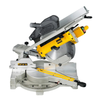
Turning the Sawhead and Table Over (Fig. F1–F4)
1. Hold the saw table
21
with one hand and push the table release lever
2
to the right
(Fig.F1).
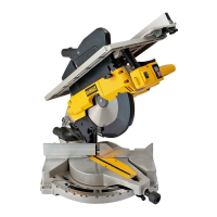
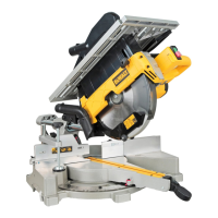
2. Push the table downwards at the front (Fig. F2) and swing it over completely until the
motor assembly is uppermost and the plate
55
engages in the table locking device
56
(Fig. F3).
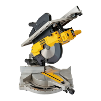
3. Push the release lever
57
to the rear whilst holding down the head until the spring-
loaded bearing unit
58
can be lifted out of its seating (Fig. F4).
4. Flip the bearing unitup.
5. Holding the head firmly, allow the spring pressure to take the head upwards into its
restposition.
Mounting the Saw Blade (Fig. G1–G4)
WARNING: To reduce the risk of injury, turn unit off and disconnect machine from
power source before installing and removing accessories, before adjusting or
changing set-ups or when making repairs. An accidental start-up can causeinjury.
WARNING:
• Always change blades with the machine in mitre sawmode.
• Never depress the spindle lock button while the blade is under power orcoasting.
• Do not cut ferrous metal (containing iron or steel) or masonry or fibre cement product
with this mitresaw.
• The teeth of a new blade are very sharp and can bedangerous.
• Depress the head lock up release lever
9
to release the lower guard
8
, then raise the
lower guard as far as possible (Fig.G1).
1. With the lower guard held in the raised position, depress the spindle lock button
60
with
one hand, then use the supplied blade spanner in the other hand to loosen the left-hand
threaded blade locking screw
59
by turningclockwise.
WARNING: To use the spindle lock, press the button as shown and rotate the spindle by
hand until you feel the lockengage.
2. Continue to hold the lock button in to keep the spindle from turning (
60
, Fig.G1).
3. Remove the blade locking screw
59
and the outside arbor collar
61
.
4. Install the saw blade
62
onto the shoulder
63
provided on the inside arbor collar
64
,
making sure that the teeth at the bottom edge of the blade are pointing toward the back
of the saw (away from the operator).
5. Replace the outer arbor collar
61
.
6. Tighten the blade locking screw
59
carefully by turning counter-clockwise while holding
the spindle lock engaged with your otherhand.
7. Raise the lowerguard.
WARNING: Be aware the saw blade shall be replaced in the described way only. Only use
saw blades as specified under Technical Data; Cat.no.: DT4260 issuggested.
Adjustments for Mitre Saw Mode
Your mitre saw was accurately adjusted at the factory. If readjustment due to shipping and
handling or any other reason is required, follow the steps below to adjust your saw. Once
made, these adjustments should remainaccurate.
Checking and Adjusting the Blade to the Fence (Fig. H1–H3)
1. Loosen the mitre knob
65
and depress the mitre latch
66
to release the rotating table
5
(Fig. H1).
2. Swing the rotating table until the latch locates it at the 0° mitre position. Do not tighten
theknob.
3. Pull down the head until the blade just enters the saw kerf
67
.
4. Place a square
68
against the left side
7
of the fence and blade
62
(Fig. H2).
WARNING: Do not touch the tips of the blade teeth with thesquare.
If adjustment is required, proceed as follows:
1. Loosen the screws
69
(Fig. H3) and move the scale/rotating table assembly left or right
until the blade is at 90° to the fence as measured with the square (Fig. H2).
2. Retighten the screws
69
(Fig. H3). Pay no attention to the reading of the mitre pointer at
thispoint.
Adjusting the Mitre Pointer (Fig. H1, H4)
1. Loosen the mitre knob
65
and depress the mitre latch
66
to release the rotating table
5
(Fig. H1).
2. With the mitre knob loose, allow the mitre latch to snap into place as you rotate the mitre
arm pastzero.
3. Observe the pointer
70
and mitre scale
71
(Fig. H4). If the pointer does not indicate
exactly zero, loosen the screw
72
, move the pointer to read 0° and tighten thescrew.
Checking and Adjusting the Blade to the Table (Fig. I1–I3)
1. Loosen the bevel clamp knob
16
(Fig. I1).
2. Press the saw head to the right to ensure it is fully vertical and tighten the bevel
clampknob.
3. Pull down the head until the blade just enters the saw kerf
67
.
4. Place a set square
68
on the table and up against the blade
62
(Fig.I2).
WARNING: Do not touch the tips of the blade teeth with thesquare.
If adjustment is required, proceed as follows:
1. Loosen the bevel clamp knob
16
(Fig. I1) and turn the vertical position adjustment stop
screw
73
(Fig. I3) in or out until the blade is at 90° to the table as measured with the
square (Fig. I2).
2. If the bevel pointer
74
does not indicate zero on the bevel scale
75
, loosen the screw
76
that secures the pointer and move the pointer as necessary (Fig. I3).
Adjusting the Fence (Fig. J)
The upper part of the left side of the fence can be adjusted to the left to provide clearance,
allowing the saw to bevel to a full 48° left. To adjust the fence
7
:
1. Loosen the fence clamping knob
77
and slide the upper part of the side fence to theleft.
2. Make a dry run with the saw switched off and check for clearance. Adjust the fence to
be as close to the blade as practical to provide maximum workpiece support, without
interfering with the up and down movement of thearm.
3. Tighten the knobsecurely.
WARNING: The guide groove
78
can become clogged with sawdust. Use a stick or some
low pressure air to clear the guidegroove.
Checking and adjusting the Bevel Angle (Fig. I1, J, K)
1. Loosen the fence clamping knob
77
and slide the upper part of the side fence to the left
as far as it will go (Fig. J).
2. Loosen the bevel clamp knob
16
(Fig. I1) and move the saw arm to the left until the angle
position stop
79
rests against the bevel position adjustment stop
80
(Fig. K). This is the
45° bevelposition.
If adjustment is required, proceed as follows:
1. Turn the bevel position adjustment stop screw
80
in or out as necessary until the
pointer
74
indicates 45° with the angle position stop resting against the bevel position
adjustmentstop.
Assembly for Saw Bench Mode
Changing from Mitre Saw to Saw Bench Mode (Fig. A1, A3, L1–L5)
1. Put the blade into 0° cross-cut position with the rotating table clamp
3
secured (Fig. A1).
2. Remove the riving knife
22
from its storage position in the inside of the base (Fig. A3).
3. Depress the guard release lever
9
to release the blade guard
8
, then raise the blade
guard as far as possible (Fig. A1).
4. Loosen the cap screw
81
just enough to allow riving knife to slide onto mounting
pads
82
onarm.
5. Slide the riving knife
22
onto the mounting pads
82
(Fig. L1). Tighten the cap screw
81
.
6. Unscrew the knob
77
and extract the sliding fence
7
as shown in FigureL2.
7. Pull down thesawhead.
8. Push the release lever
57
to the rear (Fig. L3).
9. Push the bearing unit
58
down until notches
83
engage in the locations
84
(Fig. L3).
WARNING: The blade should not foul the lower bladeguard.
10. Pull the table release lever
2
to the right, lift the front edge of the table
4
(Fig. L4) and
flip it back through 180° until the plate
55
of the table-locking device
56
automatically
engages the latch of the table locking device to secure it in the saw bench mode (Fig. L5).
11. Remove the under-tableguard.
Fitting the Upper Blade Guard (Fig. N)
The upper blade guard
23
is designed to be quickly and easily attached to the riving knife
22
once the machine has been set up for saw benchmode.
1. Holding the guard vertically, align the slot in the rear of the guard with the rivingknife.
2. Lower the guard over the riving knife
22
, making sure that the shaft of the bolt enters
therecess.
3. Turn the guard into horizontalposition.
WARNING: Never use your saw in saw bench mode without the upper guard
correctlyfitted.
Mounting and Adjusting the Parallel Fence (Fig. O1–O5)
The parallel fence
24
can be mounted on either side of theblade.
1. Slide the bracket
85
on from the left or the right (Fig. O1). The clamping plate engages
behind the front edge of thetable.
2. Slide the fence up against theblade.
3. Push the lever
86
down to secure the fence inplace.
4. Check that the fence is parallel to theblade.
If adjustment is required, proceed as follows:
1. Loosen the lock knobs
87
and slide the fence backwards in order to obtain access to the
adjustment bolts
88
in the top of the fence (Fig.O2).
2. Using the spanner, loosen the adjustment bolts fastening the fence bracket to the
fencesupport.
3. Adjust the fence so that it is parallel to the blade by checking the distance between the
blade and the fence at the front and rear of theblade.
4. When the adjustment has been carried out, re-tighten the adjustment bolts and check
again that the fence is parallel to theblade.
5. Check that the pointer
89
indicates zero on the scale (Fig. O3). If the pointer does not
indicate exactly zero, loosen the screw
90
, move the pointer to read 0° and tighten
thescrew.
 Loading...