ENGLISH
9
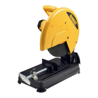
f. Depth stop bolt
g. Lock nut
h. Base
i. Fence
j. Material clamp
k. Cutting table
l. 8 mm hex key
m. Handle
n. Material clamp lever
o. Cutting disc
p. Guard
q. Spindle lock
r. Lock-down hook
s. Spark deflector
t. Spark deflector screw
u. Lock-down chain
v. Date code
INTENDED USE
Your D28710 chop saw has been designed for the
cutting of variously shaped steel materials.
DO NOT use under wet conditions or in presence of
flammable liquids or gases.
The D28710 chop saw is a professional power tool.
DO NOT let children come into contact with the
tool. Supervision is required when inexperienced
operators use this tool.
Electrical Safety
The electric motor has been designed for one
voltage only. Always check that the power supply
corresponds to the voltage on the rating plate.
Your DEWALT tool is double insulated in
accordance with EN 61029; therefore no
earth wire is required.
If the supply cord is damaged, it must be replaced
by a specially prepared cord available through the
DEWALT service organisation.
Using an Extension Cable
If an extension cable is required, use an approved
3–core extension cable suitable for the power input
of this tool (see Technical Data).The minimum
conductor size is 1.5 mm
2
; the maximum length is
30 m.
When using a cable reel, always unwind the cable
completely.
Connecting to the Mains
The mains supply to be used for this machine must
be equipped with a 16 A cut-out fuse with time delay.
Voltage Drops
Inrush currents cause short-time voltage drops.
Under unfavourable power supply conditions, other
equipment may be affected.
If the system impedance of the power supply is lower
than 0.11 Ω, disturbances are unlikely to occur.
ASSEMBLY AND ADJUSTMENTS
WARNING: To reduce the risk of
injury, turn unit off and disconnect
machine from power source before
installing and removing accessories,
before adjusting or changing set-
ups or when making repairs. Be sure
the trigger switch is in the OFF position.
An accidental start-up can cause injury.
Removing and Fitting a Cutting Disc
(fi g. 1, 2)
1. With the arm in the rest position, use the lip (w)
to slide the guard (p) back. Leave the guard
retracted (fig. 2).
2. Press and hold down the spindle lock (q) (fig. 1).
3. Rotate the cutting disc (o) until it locks.
4. Using the hex key (l), remove the bolt (x) by
turning counterclockwise and then remove the
flat washer (y) and the retaining flange (z) (fig. 2).
5. Check that the spacer (aa) is in place against
the flange (bb).
6. Replace the cutting disc (o). Make sure that the
new disc is placed onto the spacer (aa) in the
correct rotational direction.
7. Secure the blade with the retaining flange (z),
the flat washer (y) and the bolt (x).
8. Move the guard back down and release the
spindle lock (q).
9. Adjust the cutting depth as necessary.
ADJUSTING THE CUTTING DEPTH (FIG. 1)
The cutting depth can be adjusted to meet the wear
of the cutting disc.
• Make a dry run with the tool switched off and
check for clearance.
• If adjustment is required, proceed as follows:
– Loosen the lock nut (g) a few turns.

 Loading...