ENGLISH
5
Motor
Be sure your power supply agrees with the nameplate
marking. Voltage decrease of more than 10% will cause loss
of power and overheating.
tools are factory tested;
if this tool does not operate, check powersupply.
Connecting to a Power Supply
Connect this product to a 120V, 15A, polarized receptacle.
This appliance has a polarized plug (one blade is wider than
the other). This plug will fit in a polarized outlet only one
way. If the plug does not fit fully in the outlet, reverse the
plug. If it still does not fit, contact a qualified electrician to
install the properoutlet.
WARNING: Do not change the plug in any way.
If the power cord is ever damaged, take the tool
to a D
authorized service center for repair
orreplacement.
COMPONENTS (FIG. A)
WARNING: Never modify the power tool or any part
of it. Damage or personal injury couldresult.
Refer to Figure A at the beginning of this manual for a
complete list ofcomponents.
Intended Use
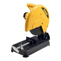
Your chop saw has been designed for the cutting of
variously shaped steelmaterials.It is designed only for use
with reinforced bonded abrasives. Diamond or TCT blades
should not be used with thisunit.
DO NOT use under wet conditions or in presence of
flammable liquids orgases.
Your chop saw is a professional power tool.
DO NOT let children come into contact with the tool.
Supervision is required when inexperienced operators use
thistool.
SPECIFICATIONS
D28730
Voltage 120V~
Frequency 60 Hz
Amps 15
No-load speed 4000/min (rpm)
Wheel diameter 14" (355 mm)
Wheel thickness .12" (3.0 mm)
Arbor size 1" (25.4 mm)
Net weight 34.1 lbs (15.5 kg)
ASSEMBLY AND ADJUSTMENTS
WARNING: To reduce the risk of serious personal
injury, turn unit off and disconnect it from
power source before making any adjustments or
removing/installing attachments or accessories.
An accidental start-up can causeinjury.
Cutting Capacity
The wide vise opening and high pivot point provide cutting
capacity for many large pieces. Use the cutting capacity
chart to determine total maximum size of cuts that can be
made with a newwheel.
CAUTION: CERTAIN LARGE, CIRCULAR OR
IRREGULARLY SHAPED OBJECTS MAY REQUIRE
ADDITIONAL HOLDING MEANS IF THEY CANNOT BE
HELD SECURELY INVISE.
CAUTION: DO NOT CUT MAGNESIUM OR WOOD
WITH THISTOOL.
Maximum Cutting Capacity
NOTE: Capacity shown on chart assumes no wheel wear
and optimum fenceposition.
Workpiece
Shape
A
A
A
A
A
90° Cutting
angle
A = 4-7/8"
(125 mm)
A = 4-1/2"
(115 mm)
4-1/2" x 5-1/8"
(115 mm x 130 mm)
A = 4-3/4"
(120 mm)
45° Cutting
angle
A = 4-1/2"
(115 mm)
A = 3-13/16"
(98 mm)
3-3/4" x 4-1/8"
(95 mm x 105 mm)
A = 4-1/8"
(105 mm)
OPERATION
WARNING: To reduce the risk of serious personal
injury, turn unit off and disconnect it from
power source before making any adjustments or
removing/installing attachments or accessories.
An accidental start-up can causeinjury.
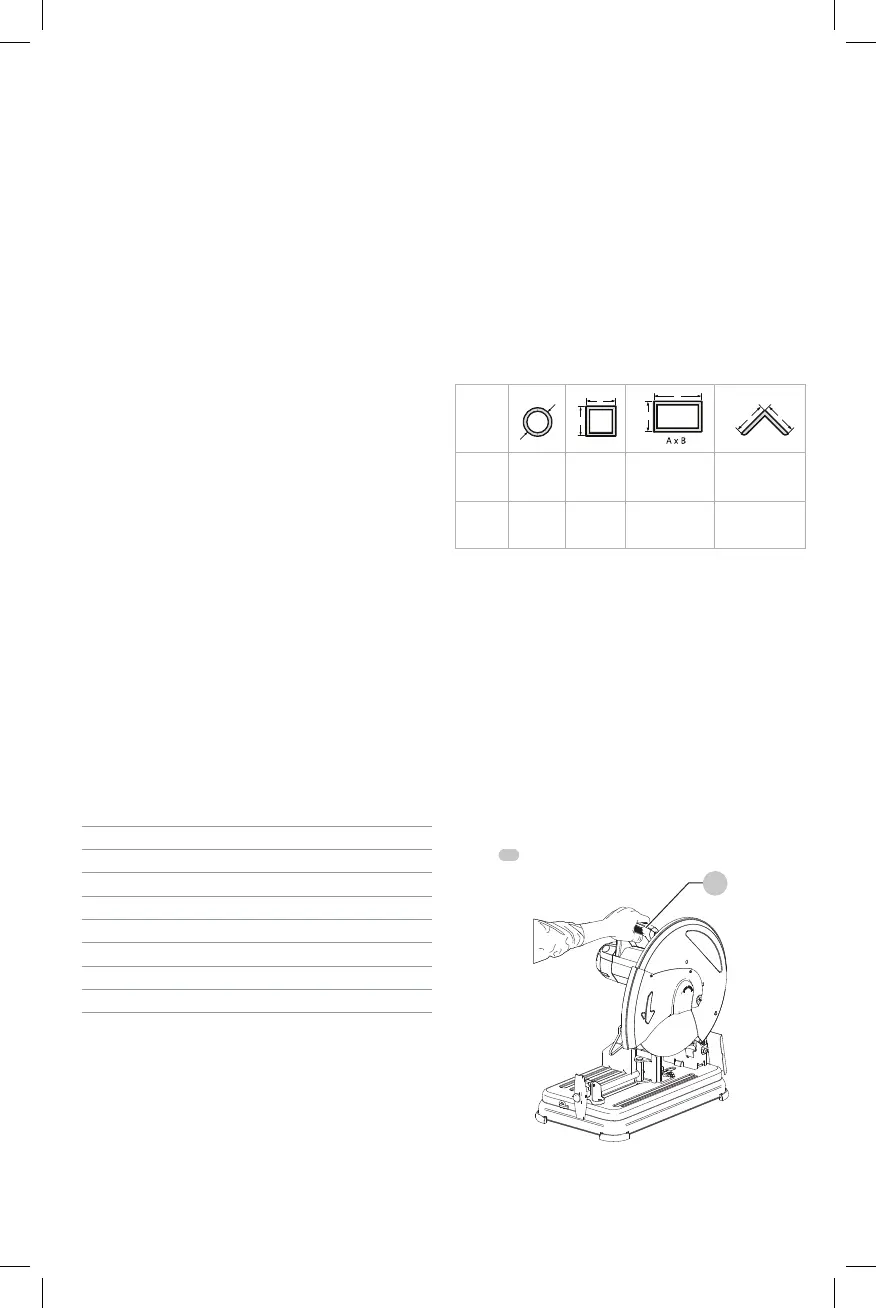
Proper Hand Position (Fig. B)
WARNING: To reduce the risk of serious personal injury,
ALWAYS use proper hand position as shown.
WARNING: To reduce the risk of serious personal injury,
ALWAYS hold securely in anticipation of a sudden
reaction.
Proper hand position requires one hand on the operating
handle
17
.
Fig. B
17

 Loading...