ENGLISH
6
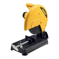
Carrying the Chop Saw (Fig. A)
Fold down unit to position where you can carry the saw.
Push in lock pin
1
to lock armdown. Always carry the saw
using the carrying handle
18
.
Unlocking (Fig. A)
To unlock tool and raise head, depress motor arm slightly
and pull lock pin
1
out. Motor arm will then pivotupward.
Mounting (Fig. A)
CAUTION: Tool must be supported on stable, level,
non-skid surface to prevent unexpected movement
whenoperating.
1. Drill holes through the work surface that align the base
of the chopsaw.
2. Insert two 5/16" (M10) bolts down through the
mounting holes
16
in the base and through holes
in mounting surface. The approximate length of the
screws should be the thickness of the mounting surface
plus 4" (102mm).
Spark Deflector Adjustment (Fig. A)
WARNING: Do not touch the spark deflector
during or immediately after operation as it
becomes hot and may cause skin burn.
To best deflect sparks away from surrounding persons and
materials, loosen the spark deflector screw
2
, adjust the
spark deflector
3
and then retighten screw. Do not allow
cordset to come into contact with deflector or sparks as
damage to cordset mayoccur.
Lock-Off Trigger Switch (Fig. A)
To turn the saw on, push the lock-off lever
14
to the left,
then depress the lock-off trigger switch
13
. The saw will
run while the switch is depressed. Allow the blade to spin
up to full operating speed before making the cut. To turn
the saw off, release the switch. Keep hands and material
away from the wheel until it has coasted to a stop. Allow
the blade to stop before raising the saw head. There is no
provision for locking the switchon.
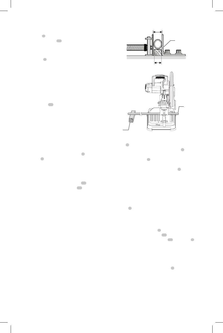
Material Clamping and Supporting
(Fig. C, D)
• Angles are best clamped and cut with both legs resting
againstbase.
• A spacer block slightly narrower than the workpiece can
be used to increase wheel utilization (Fig.C).
• Long workpieces must be supported by a block so it will
be level with top of base (Fig. D). The cut off end should
be free to fall downward to avoid wheelbinding.
Diameter of workpiece
Fig. C
Width of space block
Space block
Fig. D
Block
Cut-off end
Vise Operation (Fig. A)
The vise
6
has a quick-travel feature. To release the
vise when it is clamped tightly, turn the crank
8
counterclockwise one or two times to remove clamping
pressure. Lift vise lever
9
up. Pull crank assembly out as far
as desired. Vise may be pushed forward into work without
cranking. Lower vise lever then tighten vise
6
on work by
usingcrank.
Fence Operation (Fig. A, E, F)
WARNING: Turn off and unplug the tool before
making any adjustments or removing or
installing attachments or accessories. Be sure the
trigger switch is in the OFFposition.
The fence
5
can be adjusted two ways: to change desired
cutting angle and to change spacing between the fence
andvise.
To Change the Desired Cutting Angle
Use the 5/16" (8mm) hex key
7
provided to loosen (do
not remove) the two fence bolts
15
. Align the desired
angle indicator line with the slot line
26
in the base
4
.
Securely tighten both fence bolts before use. For more
accurate square cuts, disconnect the power supply, loosen
the two fence bolts, push arm down until wheel extends
into base. Place a square against the wheel and adjust fence
against the square. Securely tighten both fence bolts before
use. When making a miter cut, the vise
6
may not clamp
securely, depending on the thickness of the workpiece and
the miter angle. Other aids (such as spring, bar or C-clamps)
will be necessary to secure the workpiece to the fence when
making thesecuts.

 Loading...