ENGLISH
7
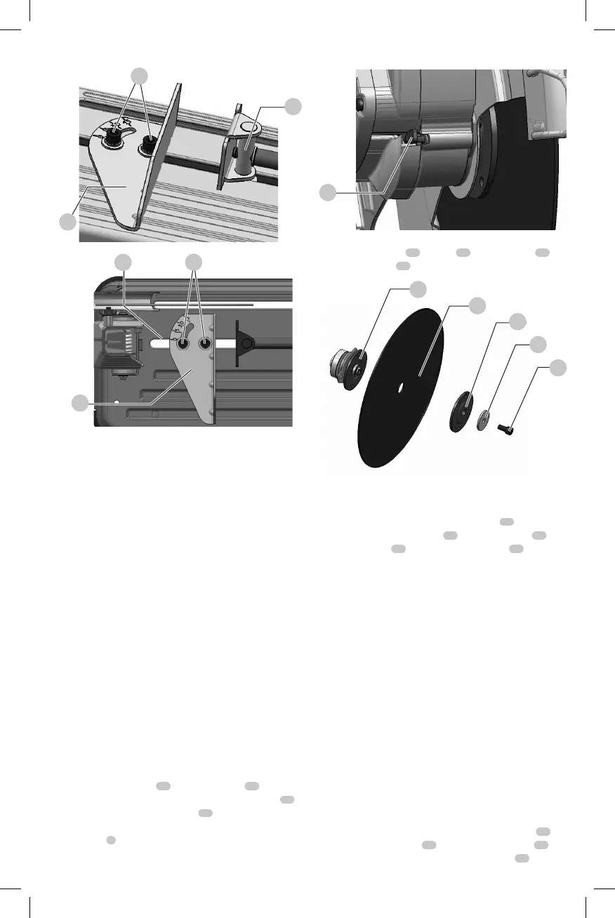
Fig. E
6
5
15
Fig. F
5
15
26
Removal and Installation of Wheels
(Fig. G, H)
WARNING: Turn off and unplug the tool before
making any adjustments or removing or
installing attachments or accessories. Be sure the
trigger switch is in the OFF position. Do not make
any adjustment while the wheel is in motion. Do not
make any adjustment while chop saw is plugged into
powersupply.
WARNING: Use only bonded reinforced cut-off wheels
for your power tool. A bonded reinforced wheel is
defined as a grinding wheel consisting of abrasive
particles bonded together with various substances
specifically for cutting steelmaterials.
WARNING: Always use gloves when
handlingwheels.
WARNING: Handle and store all abrasive wheels
carefully to prevent damage from thermal shock, heat,
mechanical damage, etc. Store in a dry protected area
free from high humidity, freezing temperatures or
extreme temperaturechanges.
WARNING: Do not impact the wheel, and do not use
a wheel that has been dropped or impacted. Do not
use a chipped, deformed or damagedwheel.
1. Push in spindle lock
12
and rotate wheel
10
by hand
until wheel lock lever engages slot in inside flange
27
to lock wheel. Loosen the bolt
19
counterclockwise in
the center of the abrasive wheel with the 5/16" (8mm)
hex key
7
. Bolt has right-handthread.
Fig. G
12
2. Remove the bolt
19
, washer
20
, outside flange
21
and old wheel
10
.
Fig. H
19
20
21
10
27
3. Make sure flange surfaces are clean and flat. Install the
new abrasive wheel by reversing the abovesteps.
4. For safe operation, securely tighten bolt
19
to firmly
secure the abrasive wheel
10
in between inner
18
and
outer flanges
21
. Do not overtightenbolt
19
.
WARNING: Check the work surface that the chop saw
rests on when replacing with a new abrasive wheel. It
is possible that the wheel may contact ANY ITEMS OR
STRUCTURE THAT EXTENDS ABOVE work surface
(under the base) when the arm is fullylowered.
Operation Tips for More Accurate Cuts
• Allow the wheel to do the cutting. Excessive force will
cause the wheel to glaze reducing cutting efficiency
and/or to deflect causing inaccuratecuts.
• Properly adjust fenceangle.
• Make sure material is laying flat acrossbase.
• Properly clamp material to avoid movement
andvibration.
Motor Brush Inspection and Replacement
(Fig. I, J)
BE SURE TOOL IS UNPLUGGED BEFORE INSPECTING
BRUSHES. Brushes should be regularly inspected for wear.
To inspect brushes, unscrew the two end cap screws
22
and remove the end cap
23
. To remove each brush
24
,
first unplug the shunt wire terminal connection
25
. Then

 Loading...