9
ENGLISH
Blades
This portable band saw is setup for use with .02"
(0.5mm) thick, 1/2" (12.7 mm) wide and 27"–27-1/4"
(686mm–692mm) long blades. DO NOT use .025"
(0.64mm) thickblades.
WARNING: The use of any other blade or accessory
might be hazardous. DO NOT use any other type
of accessory with your band saw. Blades used on
Blade Tracking (Fig. A, E, G)
WARNING: To reduce the risk of serious personal
injury, turn tool off and remove the battery pack
before making any adjustments or removing/
installing attachments or accessories. An
accidental start‑up can causeinjury.
NOTICE: Excessive tightening of the adjustment screws
could result in damage to thesaw.
Your band saw is equipped with an adjustable blade tracking
mechanism which assures proper blade tracking at all times.
The blade is properly adjusted when it is sitting fully on
rubber tires
19
and lightly touching one or both of the rear
guide bearings
18
.
To Adjust the Blade Tracking
1. Turn and open the blade tension lever
7
to allow access
to the tracking screw
12
.
2. Use a 10mm wrench to loosen the locking nut
6
(Fig.G).
3. Use a 3mm hex wrench
4
to turn the tracking screw
12
1/4 turn clockwise or counterclockwise (Fig.G).
NOTE: Turning the tracking screw clockwise moves
the blade toward the guide roller, turning the tracking
screw counterclockwise moves the blade away from the
guideroller.
4. Tighten the locking nut and close the blade tension lever
and blade guard. (It will be necessary to run the saw to
observe the tracking.)
5. Observe blade tracking between runs and repeat Steps
1–4 as necessary to achieve proper bladetracking.
ASSEMBLY AND ADJUSTMENTS
WARNING: To reduce the risk of serious personal
injury, turn unit off and remove the battery pack
before making any adjustments or removing/
installing attachments or accessories. An
accidental start‑up can causeinjury.
exposed. Align the slots on the back of the charger with the
exposed screws and fully engage them in theslots.
SAVE THESE INSTRUCTIONS FOR
FUTURE USE
Installing and Removing Blades
CAUTION: Cut Hazard. Blade tension lever is under
spring pressure. Maintain control of lever when
releasing bladetension.
WARNING: ALWAYS wear gloves when touching the
sawblade.
To Install Blade (Fig. A, D–F)
1. Rotate the blade tension lever
7
clockwise 180degrees
until it stops to release tension on blade (refer to
FigureA).
2. Turn the saw over and place it on a workbench ortable.
3. Unlatch the two blade guard latches
11
and open the
bladeguard.
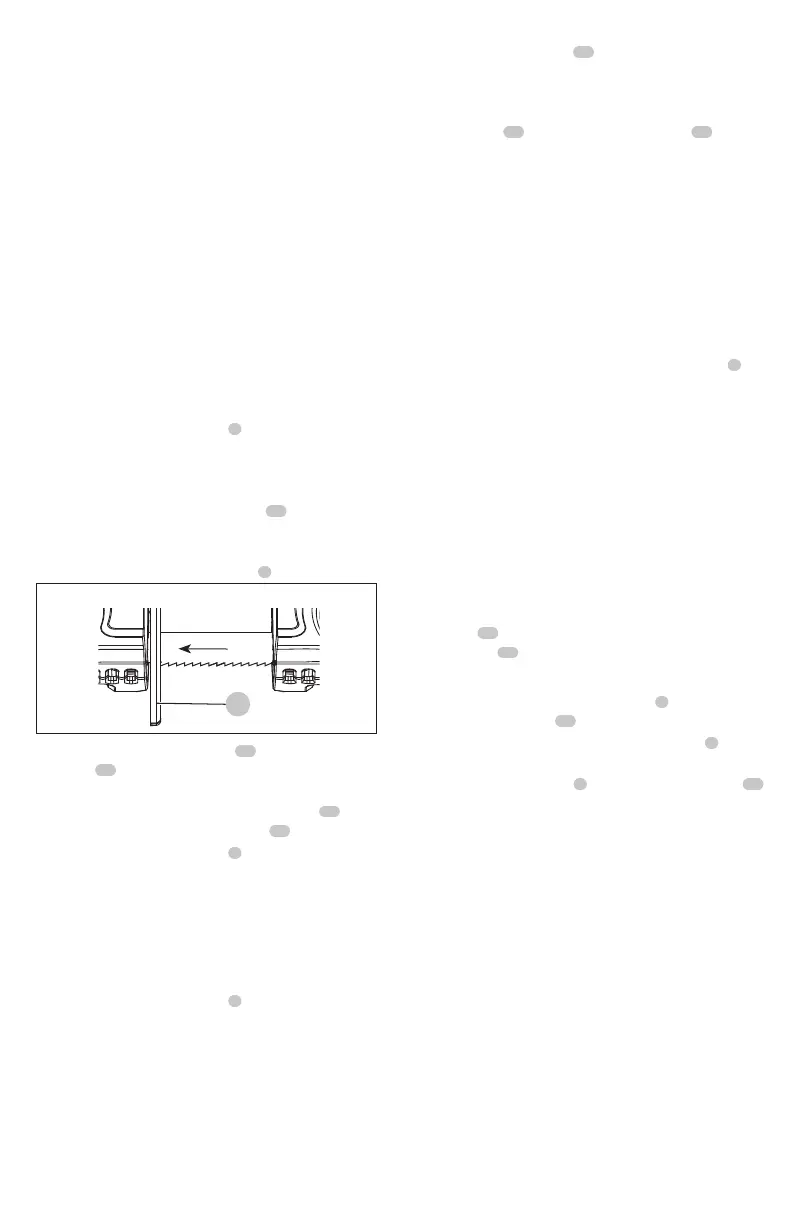
4. Position the blade so that the teeth face out from the
saw and cut towards the work stop
5
.
blade direction
5
5. Slip blade into the guide rollers
17
and around both
pulleys
16
as shown in FigureD.
6. Make sure that the blade is fully inserted into the guide
rollers and positioned fully on the rubbertires
19
and
just touching the rear guide bearings
18
.
7. Rotate the blade tension lever
7
counterclockwise until
it stops and then close blade guard and secure latches.
Make sure the teeth face away from the band saw
(Fig.A,D).
8. Turn the saw on and off a few times to ensure that the
blade is seatedproperly.
To Remove Blade (Fig. A, D–F)
1. Rotate the blade tension lever
7
clockwise 180degrees
until it stops to release tension in blade (refer to
FigureA).
2. Turn the saw over and place it on a workbench ortable.
3. Unlatch the two blade guard latches and open the
bladeguard.
4. When removing the blade, tension may be released and
the blade may spring free. SAW BLADES ARE SHARP. USE
CARE IN HANDLINGTHEM.
5. Inspect the guide rollers
17
and remove any large chips
which may be lodged in them. Lodged chips can prevent
rotation of the guide rollers and cause flat spots on the
guiderollers.
6. Rubber tires
19
are mounted on the pulleys
16
. The
rubber tires should be inspected for looseness or damage
when changing the blade. Wipe any chips from the
rubber tires on the pulleys with abrush.
NOTE: Do not use your hands to wipechips.
This will extend tire life and keep the blade from slipping.
If any looseness or damage occurs, the tool should be
brought to an authorized DeWALT service center for
repair or replacement as soon as possible. Continued use
of the tool with loose or damaged rubber tires will cause
unstable travel of the band sawblade.
7. Close the blade guard and securely latch the two
blade guard latches. Rotate the blade tension lever
7
counterclockwise 180degrees until itstops.