ENGLISH
10
ASSEMBLY AND ADJUSTMENTS
WARNING: To reduce the risk of serious personal
injury, turn unit off and remove the battery pack
before making any adjustments or removing/
installing attachments or accessories. An
accidental start-up can causeinjury.
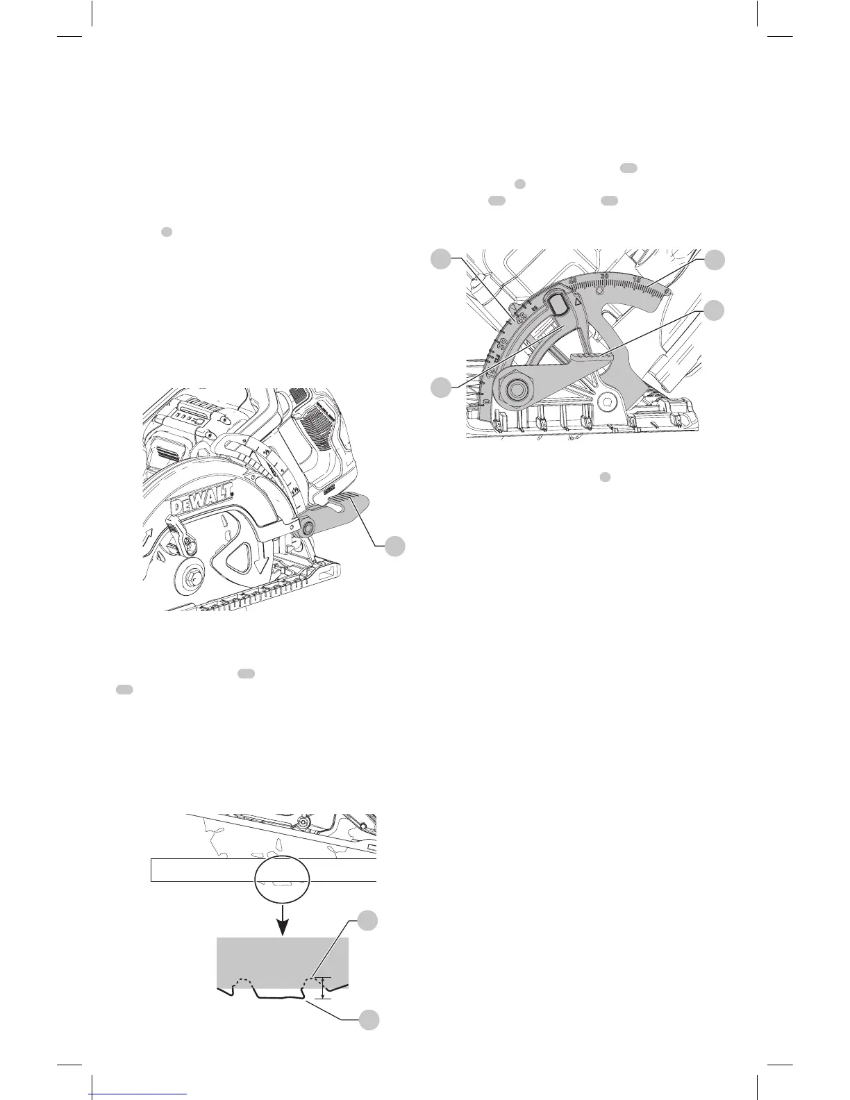
Cutting Depth Adjustment (Fig. A, E, F)
1. Hold the saw firmly. Lift the depth adjustment locking
lever
3
to move foot plate to obtain the desired depth
ofcut.
2. Lower the depth adjustment locking lever and tighten
securely to lock the depth of cut before operatingsaw.
The length of cut markings on the side of the foot plate are
accurate at full depth of cut only. Setting the saw at the
proper cutting depth keeps blade friction to a minimum,
removes sawdust from between the blade teeth, results in
cooler, faster sawing and reduces the chance ofkickback.
Fig. E
3
For the most efficient cutting action, set the depth
adjustment so that half of a blade tooth will project below
the material to be cut (refer to Figure F). This distance is
from the tip of the tooth
27
to the bottom of the gullet
28
(refer to inset of FigureF). This keeps blade friction at a
minimum, removes sawdust from the cut, results in cooler,
faster sawing and reduces the chance of kickback. A method
for checking for correct cutting depth is shown in FigureF.
Lay a piece of the material you plan to cut along the side of
the blade, as shown, and observe how much tooth projects
beyond thematerial.
Fig. F
28
27
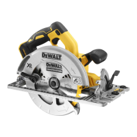
Bevel Angle Adjustment (Fig. A, G)
The full range of the bevel adjustment is from 0˚ to
53˚. Detents are located at 22.5˚ and 45˚. The angle
quadrant is graduated in increments of 1˚. On the front
of the saw is a bevel angle adjustment mechanism which
consists of a calibrated angle quadrant
10
and a bevel
adjustment lever
9
. The angle quadrant allows for coarse
adjustment
16
or fine adjustment
17
to achieve better
accuracy incutting.
Fig. G
16
17
9
10
To set the saw for a bevel cut
1. Lift the bevel adjustment lever
9
and tilt foot plate
to the desired angle by aligning the pointer with the
desired anglemark.
2. Push the bevel adjustment lever down and tighten
securely to lock theangle.
Foot Plate Adjustment for 90˚ Cuts
(Fig. H)
If additional adjustment is needed
1. Adjust the saw to 0˚bevel.
2. Retract blade guard. Place the saw on bladeside.
3. Lift bevel adjustment lever. Place a square
against the blade and foot plate to adjust the
90˚setting.
4. Move the adjustment screw, located on the bottom of
the foot plate (Fig.H), so that the foot plate will stop at
the properangle.
5. Confirm the accuracy of the setting by checking the
squareness of an actual cut on a scrap piece ofmaterial.