ENGLISH
4
The label on your tool may include the following symbols. The
symbols and their definitions are asfollows:
V ......................... volts
Hz .......................hertz
min ..................... minutes
or DC ......direct current
...................... Class I Construction
(grounded)
…/min ..............per minute
BPM ....................beats per minute
IPM ..................... impacts per minute
RPM .................... revolutions per
minute
sfpm ................... surface feet per
minute
SPM .................... strokes per minute
A ......................... amperes
W ........................watts
or AC ...........alternating current
or AC/DC .... alternating or
direct current
...................... Class II
Construction
(double insulated)
n
o
........................no load speed
n .........................rated speed
......................earthing terminal
.....................safety alert symbol
.....................visible radiation
..................... wear respiratory
protection
..................... wear eye
protection
..................... wear hearing
protection
SAVE THESE INSTRUCTIONS FOR
FUTURE USE
Motor
Be sure your power supply agrees with the nameplate
marking. Voltage decrease of more than 10% will cause loss
of power and overheating.
tools are factory tested;
if this tool does not operate, check power supply.
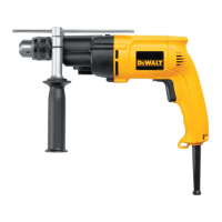
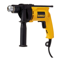
COMPONENTS (FIG. A)
WARNING: Never modify the power tool or any part
of it. Damage or personal injury couldresult.
Refer to Figure A at the beginning of this manual for a
complete list ofcomponents.
INTENDED USE
These heavy-duty V.S.R. drills are designed for
professionaldrilling.
DO NOT use under wet conditions or in presence of
flammable liquids orgases.
This hammerdrill is a professional power tool.
DO NOT let children come into contact with the tool.
Supervision is required when inexperienced operators use
thistool.
ASSEMBLY AND ADJUSTMENTS
WARNING: To reduce the risk of serious personal
injury, turn unit off and disconnect it from
power source before making any adjustments or
removing/installing attachments or accessories.
An accidental start-up can causeinjury.
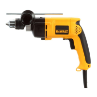
Side Handle (Fig. A)
WARNING: To reduce the risk of personal injury,
ALWAYS operate the tool with the side handle
properly installed. Failure to do so may result in
the side handle slipping during tool operation and
subsequent loss of control. Hold tool with both hands
to maximizecontrol.
A side handle
5
is supplied with this hammerdrill. It clamps
to the front of the gear case as shown in FigureA and can
be rotated 360˚ for right- or left- handuse.
Switch (Fig. B)
WARNING: Be sure to release the locking mechanism
before disconnecting the plug from the power supply.
Failure to do so will cause the hammerdrill to start
immediately the next time it is plugged in. Damage or
personal injury couldresult.
To start hammerdrill, depress the trigger switch
1
. To stop
hammerdrill, release the triggerswitch.
To lock the trigger switch in the ON position for continuous
operation, depress the trigger switch and push up the
locking button
2
. The tool will continue to run. To turn the
tool OFF, from a locked-on condition, squeeze and release
the trigger once. Before using the tool (each time), be sure
that the locking button release mechanism is workingfreely.
DO NOT lock the switch on when drilling by hand so that
you can instantly release the trigger switch if the bit binds
in the hole. The locking button is for use only when the
hammerdrill is mounted in a drill press stand or other wise
heldstationary.
Fig. B
1
2
3
Variable Speed
The variable speed trigger switch permits speed control. The
farther the trigger switch is depressed, the higher the speed
of thehammerdrill.
NOTE: Use lower speeds for starting holes without a
centerpunch, drilling in metal, plastics or ceramics, or
driving screws. Higher speeds are better for drilling in
wood and composition board and for using abrasive and
polishingaccessories.