14
ENGLISH
Clamping the Workpiece (Fig. U–W, BB)
WARNING: A workpiece that is clamped, balanced and secure before a cut may become
unbalanced after a cut is completed. An unbalanced load may tip the saw or anything the
saw is attached to, such as a table or workbench. When making a cut that may become
unbalanced, properly support the workpiece and ensure the saw is firmly bolted to a
stable surface. Personal injury mayoccur.
WARNING: The clamp foot must remain clamped above the base of the saw whenever
the clamp is used. Always clamp the workpiece to the base of the saw – not to any other
part of the work area. Ensure the clamp foot is not clamped on the edge of the base of
thesaw.
CAUTION: Always use a workpiece clamp to maintain control and reduce the risk of
personal injury and workpiecedamage.
Use the workpiece clamp
34
provided with your saw. Other aids such as spring clamps, bar
clamps or C-clamps may be appropriate for certain sizes and shapes of material. The left side
fence will slide from side to side to aid insecuring.
To Install Clamp
1. Insert the workpiece clamp into the hole lateral to the mitrefence.
2. Rotate the clamp arm toward to the front of the mitresaw.
3. Loosen the knob to adjust the clamp up and down and secure it in the choosenheight.
4. Use the fine adjust knob to firmly clamp theworkpiece.
NOTE: Place the clamp on the right side of the base when beveling. ALWAYS MAKE DRY RUNS
(UNPOWERED) BEFORE FINISH CUTS TO CHECK THE PATH OF THE BLADE. ENSURE THE CLAMP
DOES NOT INTERFERE WITH THE ACTION OF THE SAW ORGUARDS.
General Handling
• In the mitre saw mode, the sawhead is automatically locked in the upper "park"position.
• Squeezing the guard release lever will unlock the sawhead. Moving the sawhead down
retracts the moveable lowerguard.
• Never seek to prevent the lower guard returning to its park position when the cut
iscompleted.
• The minimum length of offcut material is 10mm.
• When cutting UPVC sections, a supporting piece made out of timber with a
complementary profile should be placed beneath the material being cut to provide the
correct level ofsupport.
Vertical Straight Cross Cut (Fig. U)
1. Set the rotating table to 0° and make sure that the locating plunger isengaged.
2. Tighten the rotating table clampingknob.
3. Place the wood to be cut against the fence. Take hold of the control handle and press in
the guard retractionlever.
4. Switch the machineon.
5. Allow the blade to cut freely. Do notforce.
6. After completing the cut, release the switch and wait for the saw blade to come to a
complete standstill before returning the head to its upper restposition.
7. Release the guard retractionlever.
WARNING: Do not allow the sawhead to jump back unaided to preventdamage.
Mitre Cuts (Fig. V)
1. Set the required mitreangle.
2. Ensure that the rotating table clamp is tightlysecured.
3. Proceed as for a vertical straight cross-cut.
4. Prevent the blade cutting the table if the angle is not 45°.
WARNING: When mitring the end of a piece of wood with a small off-cut, position the
wood to ensure that the off-cut is to the side of the blade with the greater angle to the
fence: left mitre, off-cut to the right mitre, off-cut to theleft.
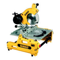
Bevel Cuts (Fig. A, W)
1. Release the bevel clamp knob
24
and tilt the head to the anglerequired.
2. Tighten the bevel clamphandle.
3. Proceed as for a vertical straight cross-cut.
Compound Mitre
This cut is a combination of a mitre and a bevel cut. The limitations are 35° mitre/30° bevel. Do
not exceed theselimits.
Set the bevel angle and subsequently set the mitreangle.
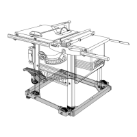
Sawing in the Bench Mode
• Always use the rivingknife.
• Always ensure that the riving knife and blade guard are correctlyaligned.
• Always ensure that the mitre saw is set and locked in 0°mitre.
WARNING: DO NOT cut any type of metalmaterial.
Ripping (Fig. A, X)
1. Set the bevel angle to 0°.
2. Adjust the saw blade height. The correct blade position is to have the tips of three teeth
above the top surface of thewood.
3. Set the parallel fence to the requireddistance.
4. Hold the workpiece flat on the table and against the fence. Keep the workpiece approx.
25mm away from the sawblade.
5. Keep both hands away from the path of the sawblade.
6. Switch the machine on and allow the saw blade to reach fullspeed.
7. Slowly feed the workpiece underneath the upper blade guard, keeping it firmly pressed
against the fence. Allow the teeth to cut, and do not force the workpiece through the saw
blade. The saw blade speed should be keptconstant.
8. Remember to use the push stick
19
when close to theblade.
9. After completing the cut, switch the machine off, allow the saw blade to stop and remove
theworkpiece.
WARNING: Never push or hold the free or cut-off side of theworkpiece.
WARNING: Always use a push stick when ripping smallworkpieces.
Bevel Cuts (Fig. Y)
1. Release the bevel clamp knob and set the blade to the requiredangle.
2. In order to prevent material jamming between the blade and the fence, position the fence
to the left of theblade.
3. Proceed as for verticalripping.
Mitre Cuts (Fig. Z1–Z3)
1. To adjust the mitre fence, loosen the stop screw locknut
76
and screw the stop
72
in or
out until the mitre pointer reads 0° (Fig. Z1).
2. Set the blade height andangle.
3. Insert the slide bar
73
of the mitre fence into the groove
74
provided in the left-hand
side of the table (Fig. Z2).
4. Loosen the mitre locking knob
75
and rotate the fence to set the scale to the required
angle (Fig. Z3).
5. Tighten the mitre locking knob
75
.
6. Place the workpiece against the flat surface of the mitre fence. Switch on and, holding the
workpiece firmly, slide the fence along the groove to take the workpiece into the blade.
When the cut is completed, switch offimmediately.
Fence Positions, Bench Saw Mode (Fig. AA)
• For ripping thin materials, use the 11 mm profile of the dual height parallel fence and
position the fence opposite the front edge of the rivingknife.
• For ripping thicker materials, use the 62 mm profile of the dual height parallelfence.
• For cross-cutting narrow and short workpieces (Fig. AA):
- Adjust the parallel fence with the low profile facing the blade and install the rear of the
fence in line with the leading edge of theblade.
- Set the workpiece against the mitre fence (at 0° or 90°) and push the mitre fence to
make thecut.
- To prevent small offcut pieces fouling against the blade, prepare a tapered length of
timber and clamp it on the rear edge of the worktable close enough to the right-hand
side of the blade so that successive offcuts feed automatically to theright.
• For ripping narrow (< 120 mm) and long workpieces:
- Place the fence in rearmost position to maintain accuracy during longcuts.
- Push the workpiece with both hands (one on each side of the blade).
- Use a push stick when close to theblade.
- Support long workpieces at the outfeedside.
• For ripping wider (> 120 mm) workpieces:
- Adjust the fence forward as in figure W if the material being cut tends to jam between
the blade or the riving knife and thefence.
Optional Attachments
WARNING: Prior to assembling any accessories always unplug themachine.
WARNING: Since accessories, other than those offered by D
WALT, have not been tested
with this product, use of such accessories with this tool could be hazardous. To reduce the
risk of injury, only D
WALT, recommended accessories should be used with thisproduct.
Dust Extraction Kit (Fig. A, E)
This machine is provided with three dust extraction points for use in mitre mode and two in
benchmode.
• When sawing wood, always connect a dust extraction device designed in accordance with
the relevant regulations regarding dustemission.
WARNING: Whenever possible, connect a dust extraction device designed in accordance
with the relevant regulations regarding dustemission.
Connect a dust collection device designed in accordance with the relevent regulations. The air
velocity of externally connected systems shall be 20 m/s +/- 2 m/s. Velocity to be measured in
connection tube at the point of connection, with the tool connected but notrunning.
A seperate dust kit
36
is available as an option (DE3500)
1. Fit the dust extraction tube to the nozzles; the longer hose to uppernozzle.
2. Connect the hoses to the three wayconnector.
Connecting - Mitre Saw Position
1. Connect one hose to the under-tableguard.
2. Connect one hose to the small diameter outlet and one to the large diameter outlet using
the correspondingspouts.
3. Connect the hoses to the 3-wayconnector.
4. Connect the single outlet of the 3-way connector to the hose from the dustextractor.
 Loading...