7
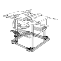
FIG. 3
A
B
D
E
F
G
H
I
N
J
K
M
L
N
O
P
C
Q
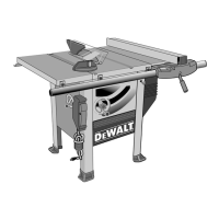
FIGURE 3
A. Table J. Bevel lock lever
B. Miter gauge K. On/off switch
C. Blade L. Rip fence indicator
D. Blade guard assembly M. Adjustable feet
E. Fence N. Mounting holes
F. Fence rails O. Cord wrap
G. Rip fence front latch P. Handle
H. Fine adjustment knob Q. Anti-kickback assembly
I. Blade height adjustment wheel
FIG. 4
W
S
R
D
T
V
U
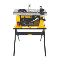
FIGURE 4
R. Rip fence rear latch V. Arbor wrench, spindle wrench
S. Dust collection port W. Rail lock lever
T. Dust shroud U. Push stick
ASSEMBLY
WARNING: Shock Hazard. To reduce the risk of serious personal injury, turn
unit off and disconnect machine from power source before attempting to move it,
change accessories or make any adjustments.