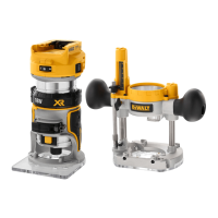
12
ENGLISH
Setting the Routing Depth (Fig.D, E)
1. Place the router with cutter fitted on to theworkpiece.
2. Set the multiple position turret stop
11
asrequired.
3. Loosen the knob quick adjustment
15
securing the
depthstop
12
.
4. Push down the plunging lock lever
6
to startplunging.
5. Lower the router slowly until the cutter touches
the workpiece and secure it in place by pushing
quickreleasebutton
7
.
Moulding Natural Timbers
WARNING: When routing always lock the plunge
lockinglever.
When edge moulding natural timbers, always mould the end
grain first, followed by the long grain.This ensures that if there is
breakout, it will be removed when the long grain isrouted.
Setting Plunge Lock System (Fig.B)
The plunge is fully automatically locking for all cuts. For heavy
cut operations, ensure to push the lever towards the toolbody.
The plunge lock lever
6
position is set at the factory so the
lever does not touch the motor body, if the plunge lock lever
begins to hit the body when the quick release lever is pushed,
readjust the locking lever position as follows:
1. Push in quick release button
7
. The plunge lever lock will
unlockautomatically.
2. Using a Torx 20star bit
39
, loosen the shoulder screw
54
on the plunge lock lever
6
with six counterclockwise turns.
Do not fullyremove.
3. Lift the plunge lock lever, rotate and reposition the plunge
lock lever at position2(at eleven o'clock).
4. Tighten the shoulderscrew.
5. If after setting to position 2sliding is not correct, repeat
steps 1to 3and reposition the lock lever at position 1.
Tighten the shoulderscrew.
WARNING: Always follow the bit manufacturer’s speed
recommendations as some bit designs require specific
speeds for safety orperformance.
If you are unsure of the proper speed or are experiencing any
type of problem, contact the bitmanufacturer.
Variable Speed Dial (Fig.A)
WARNING: If the speed control ceases to operate, or is
intermittent, stop using the tool immediately. Take it to a
DeWALT factory or authorized service facility forrepair.
NOTICE: The router is equipped with electronics to
monitor and maintain the speed of the tool while cutting.
In low and medium speed operation, the speed control
prevents the motor speed from decreasing. If you expect
to hear a speed change and continue to load the motor,
you could damage the motor by overheating. Reduce
the depth of cut and/or slow the feed rate to prevent
tooldamage.
Refer to the Speed Selection Chart to choose a router speed.
Turn the speed dial
1
to control routerspeed. The speed is
variable from 9000to 22000rpm using the speed dial
1
.
1. Turn the speed dial to the required position. The dial is
numbered from 1–7and corresponds to router speeds of
9000rpm to 22000rpm.
2. Use the slower settings for large diameter cutters and the
faster settings for small diameter cutters.
3. The correct setting will also depend on the density of the
material, depth of cut and feed speed of therouter.
NOTE: A noticeable loss of motor rpm means
motoroverload.
SPEED SELECTION CHART
DIAL SETTING APPROXIMATE RPM
1 9000
2 11000
3 13000
4 15000
5 18000
6 20000
7 22000
The speeds in this chart are approximate and are for reference
only. Your router may not produce the exact speed listed for the
dialsetting.
n
LED Worklight (Fig.F)
CAUTION: Do not stare into worklight. Serious eye
injury couldresult.
Two LED worklights
57
are located next to the collet assembly
9
.
1. The worklights
57
will constantly illuminate when the
router is connected to the mains powersupply.
2. To switch off the worklights the router must be
disconnected from mains powersupply.
NOTE: The worklight is for lighting the immediate work surface
and is not intended to be used as aflashlight.
On/Off Trigger Switch (Fig.A)
WARNING: To reduce the risk of serious personal
injury, turn unit off and disconnect it from power
source before making any adjustments or removing/
installing attachments or accessories. An accidental
start‑up can causeinjury.
1. To turn the unit on, squeeze the on/off trigger switch
3
.
Continue to squeeze the trigger switch or press the lock on
button switch
20
for continuousrunning.
2. To turn the unit off:
a. If lock on trigger is engage, release the lock on button by
squeezing and releasingtrigger.
b. If the lock on switch is not engage, fully release thetrigger.

 Loading...