99
3. When the saw comes up to speed, lower the arm smoothly and
slowly to cut through the wood. Let the blade come to a full stop
before raising arm.
SLIDING CROSSCUT
When cutting anything larger than a 51 x 150 mm (2" x 6" [51 x 105 mm
(2" x 4") at 45º mitre]) workpiece, use an out-down-back motion with the
rail lock knob (G) loosened (Fig. 18).
Pull the saw out toward you, lower the saw head down toward the
workpiece, and slowly push the saw back to complete the cut.
Do not allow the saw to contact the top of the workpiece while pulling
out. The saw may run toward you, possibly causing personal injury or
damage to the workpiece.
MITRE CROSSCUT
The mitre angle angle is often 45º for making corners, but can be set
anywhere from zero to 50º left or 60° right. Proceed as for a straight
vertical crosscut.
When performing a mitre cut on workpieces wider than 51 x 105 mm
(2" x 4") that are shorter in length, always place the longer side against
the fence (Fig. 19).
BEVEL CUT
Bevel angles can be set from 49º right to 49º left and can be cut with the
mitre arm set between 50º left or 60º right. Refer to the Features and
Controls section for detailed instructions on the bevel system.
1. Loosen the bevel lock (EE), and move the saw to the left or right as
desired. It is necessary to move the fence (N) to allow clearance.
Tighten the fence adjustment knob (M) after positioning the fences.
2. Tighten the bevel lock firmly.
At some extreme angles, the right or left side fence might have to be
removed. Refer to Fence Adjustment in the Adjustments section for
important information on adjusting the fences for certain bevel cuts.
To remove the left or right fence, unscrew the fence adjustment knob (M)
several turns and slide the fence out.
GROOVING (FIG. 1)
Your saw is equipped with a depth stop (BB), depth adjustment screw
(AA) and wing nut (Z) to allow for groove cutting.
• Flip the depth stop (BB) towards the front of the saw.
• Adjust the wing nut (Z) and depth adjustment screw (AA) to set the
depth of the groove cut.
• Place a piece of scrap material of approx. 5 cm between fence and
workpiece in order to perform a straight groove cut.
QUALITY OF CUT
The smoothness of any cut depends on a number of variables, such as
the material being cut, blade type, blade sharpness and rate of cut.
When smoothest cuts are desired for molding and other precision work,
a sharp (60 tooth carbide) blade and a slower, even cutting rate will
produce the desired results.
WARNING: Ensure that the material does not move or creep while
cutting; clamp it securely in place. Always let the blade come to a full
stop before raising arm. If small fibers of wood still split out at the rear
of the workpiece, stick a piece of masking tape on the wood where the
cut will be made. Saw through the tape and carefully remove tape when
finished.
Clamping the Workpiece (fig. 4)
WARNING: A workpiece that is clamped, balanced and secure before
a cut may become unbalanced after a cut is completed. An unbalanced
load may tip the saw or anything the saw is attached to, such as a table
or workbench. When making a cut that may become unbalanced, properly
support the workpiece and ensure the saw is firmly bolted to a stable
surface. Personal injury may occur.
WARNING: The clamp foot must remain clamped above the base of the
saw whenever the clamp is used. Always clamp the workpiece to the base
of the saw – not to any other part of the work area. Ensure the clamp foot
is not clamped on the edge of the base of the saw.
CAUTION: Always use a work clamp to maintain control and reduce the
risk of workpiece damage and personal injury, if your hands are required
to be within 152 mm (6") of the blade during the cut.
Use the material clamp (KK) provided with your saw. Other aids such as
spring clamps, bar clamps or C-clamps may be appropriate for certain
sizes and shapes of material. The left or right fence will slide from side to
side to aid in clamping.
TO INSTALL CLAMP
1. Insert it into the hole behind the fence. The clamp should be facing
toward the back of the mitre saw. The groove on the clamp rod
should be fully inserted into the base. Ensure this groove is fully
inserted into the base of the mitre saw. If the groove is visible, the
clamp will not be secure.
2. Rotate the clamp 180º toward the front of the mitre saw.
3. Loosen the knob to adjust the clamp up or down, then use the fine
adjust knob to firmly clamp the workpiece.
NOTE: Place the clamp on the opposite side of the base when beveling.
ALWAYS MAKE DRY RUNS (UNPOWERED) BEFORE FINISH CUTS TO
CHECK THE PATH OF THE BLADE. ENSURE THE CLAMP DOES NOT
INTERFERE WITH THE ACTION OF THE SAW OR GUARDS.
WARNING: Always use a material clamp when cutting non-ferrous
metals.
Support for Long Pieces (fig. 7)
ALWAYS SUPPORT LONG PIECES.
For best results, use the DW7023 or DW7033 leg stands (NN) to
extend the table width of your saw. Support long workpieces using any
convenient means such as sawhorses or similar devices to keep the ends
from dropping.
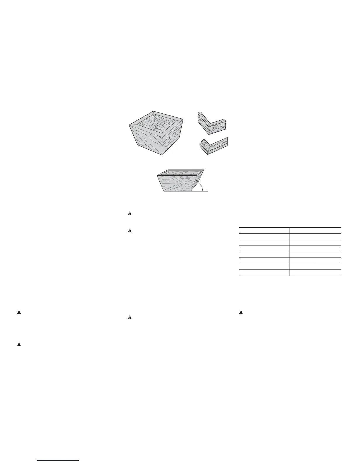
Cutting Picture Frames, Shadow Boxes And Other Four-
Sided Projects (fig. 20, 21)
Try a few simple projects using scrap wood until you develop a “feel”
for your saw. Your saw is the perfect tool for mitring corners like the one
shown in figure 20.
Sketch A in figure 21 shows a joint made with the bevel adjustment
method. The joint shown can be made using either method.
• Using bevel adjustment:
– The bevel for the two boards is adjusted to 45° each, producing a 90°
corner.
– The mitre arm is locked in the zero position and the bevel
adjustment is locked at 45º.
– The wood is positioned with the broad flat side against the table and
the narrow edge against the fence.
• Using mitre adjustment:
– The same cut can be made by mitring right and left with the broad
surface against the fence.
Cutting Trim Molding And Other Frames (fig. 21)
Sketch B in figure 21 shows a joint made by setting the mitre arm at 45º
to mitre the two boards to form a 90º corner. To make this type of joint,
set the bevel adjustment to zero and the mitre arm to 45º. Once again,
position the wood with the broad flat side on the table and the narrow
edge against the fence.
The two sketches in figure 21 are for four-sided objects only. As the
number of sides changes, so do the mitre and bevel angles. The chart
below gives the proper angles for a variety of shapes, assuming that all
sides are of equal length.
NUMBER OF SIDES MITRE OR BEVEL ANGLE
4 45°
5 36°
6 30°
7 25.7°
8 22.5°
9 20°
10 18°
For a shape that is not shown in the chart, use the following formula:
180º divided by the number of sides equals the mitre (if the material is cut
vertically) or bevel angle (if the material is cut laying flat).
Cutting Compound Mitres (fig. 22)
A compound mitre is a cut made using a mitre angle and a bevel angle at
the same time. This is the type of cut used to make frames or boxes with
slanting sides like the one shown in figure 22.
WARNING: If the cutting angle varies from cut to cut, check that the
bevel lock knob and the mitre lock handle are securely locked. These must
be locked after making any changes in bevel or mitre.
The chart (Table 1) found in the back of this manual will assist you in
selecting the proper bevel and mitre settings for common compound mitre
cuts.
• Select the desired angle A (fig. 22) of your project and locate that
angle on the appropriate arc in the chart.
• From that point follow the chart straight down to find the correct
bevel angle and straight across to find the correct mitre angle.
FIG. 20
FIG. 21
A
B
FIG. 22
ANGLE “A”