3
Electrical Connection
The electric motor has been designed for one voltage only. Always check that the power supply corresponds to the
voltage on the rating plate. 230 V AC means your tool will operate on alternating current. As little as 10% lower voltage
can cause loss of power and can result in overheating. All DEWALT tools are factory tested; if this tool does not
operate, check the power supply. Your DEWALT tool is double insulated, therefore no earth wire is required.
• Young children and the infirm. This appliance is not intended for use by young children or infirm persons without
supervision. Young children should be supervised to ensure that they do not play with this appliance
– This appliance is not intended for use by persons (including children) with reduced physical, sensory or mental
capabilities, or lack of experience and knowledge, unless they have been given supervision or instruction
concerning use of the appliance by a person responsible for their safety.
– Children should be supervised to ensure that they do not play with the appliance.
• Replacement of the supply cord. If the supply cord is damaged, it must be replaced by the manufacturer or an
authorised D
EWALT Service Centre in order to avoid a hazard.
Accessories
WARNING: Since accessories, other than those offered by DEWALT, have not been tested with this product, use
of such accessories with this tool could be hazardous. To reduce the risk of injury, only DEWALT, recommended
accessories should be used with this product.
If you need any assistance in locating any accessory, please contact: Stanley Black & Decker, 82 Taryn Drive, Epping,
VIC 3076 Australia or call 1800 444 224 or (NZ). 0800 339 258.
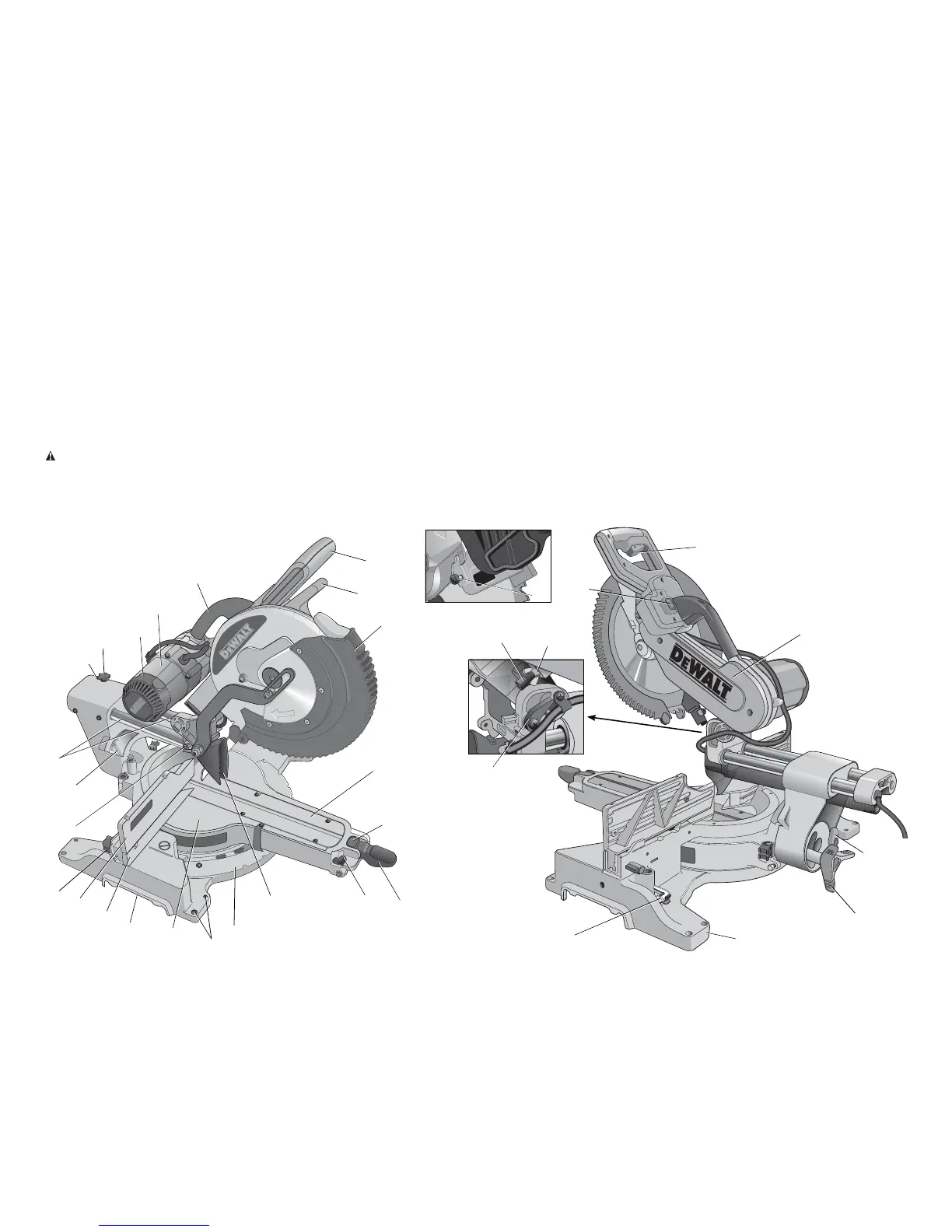
A. Lower guard
B.Guard bracket screw
C. Operating handle
D. Carrying handle
E. Motor housing
F. Motor endcap
G. Rail lock knob
H. Rail set screw adjustment
I. Head up lock lever release
J. Rails
K. Bevel scale
L. Lock down pin
M. Fence adjustment knob
N. Fence
O. Base fence
P. Hand indentation
Q. Table
R. Bench mounting holes
S. Mitre scale
T. Dust duct inlet
U. Mitre lock handle
V. Mitre latch button
W. Kerf plate
X. Trigger switch
Y. XPS
TM
on/off switch
Z. Wing nut
AA. Depth adjustment screw
BB. Depth stop
CC. Blade wrench
DD. Base
EE. Bevel lock knob
FF. 0° bevel stop
GG. Belt cover
HH. Miter latch override
AA
Z
BB
X
Y
CC
DD
EE
FF
GG
B
C
A
D
G
E
F
H
J
K
L
M
O
P
Q
R
S
T
U
V
W
N
FIG. 1
I
HH
Description (fig. 1)