11
set screw clockwise gradually while sliding the saw head back and forth. Reduce play while
maintaining minimum slide force.
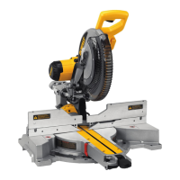
MITER LOCK ADJUSTMENT (FIG. 12)
FIG. 12
MITER LOCK
ROD
LOCK NUT
The miter lock rod should be adjusted if the
table of the saw can be moved when the
miter lock handle is locked (down). To adjust
the miter lock, put the miter lock handle in the
unlocked (up) position. Using a 1/2" (13 mm)
open end wrench, loosen the lock nut on
the miter lock rod (Fig. 12). Using a slotted
screwdriver, tighten the miter lock rod by
turning it clockwise as shown in Figure 12.
Turn the lock rod until it is snug, then turn
counterclockwise one turn. To ensure the
miter lock is functioning properly, re-lock the
miter lock to a non-detented measurement on
the miter scale – for example, 34º – and make
sure the table will not rotate. Tighten lock nut.
Support for Long Pieces
WARNING: To reduce the risk of serious personal injury, turn off the tool and
disconnect it from the power source before attempting to move it, change
accessories or make any adjustments.
ALWAYS SUPPORT LONG PIECES.
Never use another person as a substitute for a table extension, as additional support for a
workpiece that is longer or wider than the basic miter saw table or to help feed, support or
pull the workpiece.
For best results, use the DW7080 extension work support to extend the table width of your
saw, available from your dealer at extra cost. Support long workpieces using any convenient
means such as sawhorses or similar devices to keep the ends from dropping.
Cutting Picture Frames, Shadow Boxes And Other Four-
Sided Projects (Fig. 13, 14)
To best understand how to make the items listed here, we suggest that you try a few simple
projects using scrap wood until you develop a “feel” for your saw.
Your saw is the perfect tool for mitering corners like the one shown in Figure 13. Sketch A in
Figure 14 shows a joint made by using the bevel adjustment to bevel the edges of the two
boards at 45º each to produce a 90º corner. For this joint the miter arm was locked in the
zero position and the bevel adjustment was locked at 45º. The wood was positioned with the
broad flat side against the table and the narrow edge against the fence. The cut could also
be made by mitering right and left with the broad surface against the fence.
FIG. 13
A
FIG. 14
B
A
Cutting Trim Molding And Other Frames (Fig. 14)
Sketch B in Figure 14 shows a joint made by setting the miter arm at 45º to miter the two
boards to form a 90º corner. To make this type of joint, set the bevel adjustment to zero and
the miter arm to 45º. Once again, position the wood with the broad flat side on the table and
the narrow edge against the fence.
The two sketches in Figure 14 are for four-sided objects only.
As the number of sides changes, so do the miter and bevel angles. The chart below gives the
proper angles for a variety of shapes.
– EXAMPLES –
NUMBER OF SIDES MITER OR BEVEL ANGLE
4 45°
5 36°
6 30°
7 25.7°
8 22.5°
9 20°
10 18°
The chart assumes that all sides are of equal length. For a shape that is not shown in the
chart, use the following formula: 180º divided by the number of sides equals the miter (if the
material is cut vertically) or bevel angle (if the material is cut laying flat).
Cutting Compound Miters
FIG. 15
ANGLE “A”
(Fig. 15)
A compound miter is a cut made using a miter angle
and a bevel angle at the same time. This is the type of
cut used to make frames or boxes with slanting sides
like the one shown in Figure 15.
NOTE: If the cutting angle varies from cut to cut,
check that the bevel lock knob and the miter lock
handle are securely locked. These must be locked
after making any changes in bevel or miter.
The chart at the end of this manual (Table 1) will assist you in selecting the proper bevel and
miter settings for common compound miter cuts. To use the chart, select the desired angleA
(Fig. 15) of your project and locate that angle on the appropriate arc in the chart. From that
point follow the chart straight down to find the correct bevel angle and straight across to find
the correct miter angle.
Set your saw to the prescribed angles and make a few trial cuts. Practice fitting the cut pieces
together until you develop a feel for this procedure and feel comfortable with it.
Example: To make a 4-sided box with 26º exterior angles (Angle A, Fig. 15), use the upper
right arc. Find 26° on the arc scale. Follow the horizontal intersecting line to either side to
get miter angle setting on saw (42°). Likewise, follow the vertical intersecting line to the top
or bottom to get the bevel angle setting on the saw (18°). Always try cuts on a few scrap
pieces of wood to verify the settings on the saw.
Cutting Base Molding (Fig. 16)
ALWAYS MAKE A DRY RUN WITHOUT POWER BEFORE MAKING ANY CUTS.
Straight 90º cuts:
Position the wood against the fence and hold it in place as shown in Figure 16. Turn on
the saw, allow the blade to reach full speed and lower the arm smoothly through the cut.