8
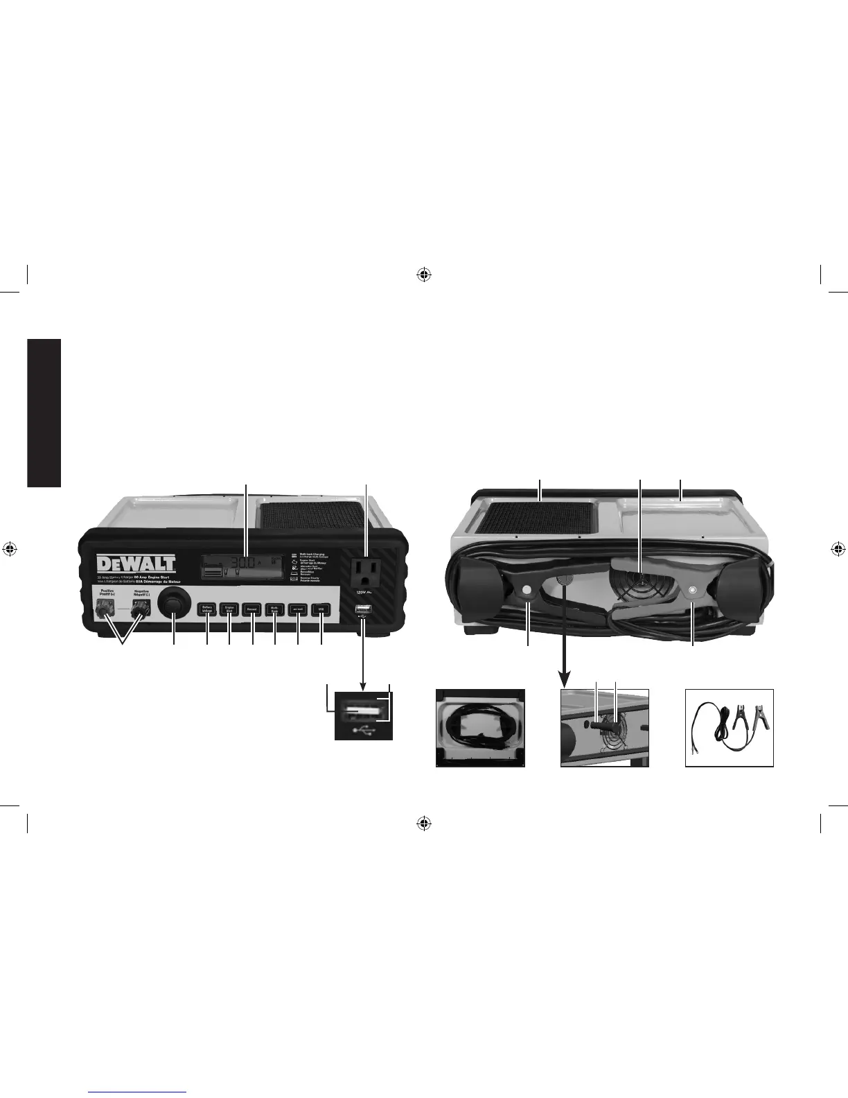
Front Panel Components (Fig. 1)
A. LCD Screen
B. AC Pass-Through
C. Bank 2 Cable Connectors
(black = negative; red =
positive)
D. Battery Charge Button
E. Battery Voltage Button
F. Engine Start Button
G. Battery Recondition Button
H. Single/Multi-Bank Selection
Button
I. Alternator Check Button
J. USB Power Button
K. USB Port
L. USB Power/Fault Indicator
LK
A B
C D F H JE G I
Back Panel Components (Fig. 2)
M. Padded Storage Tray
N. High-Speed Cooling Fan
O. Storage Tray
P. Built-in Negative Clamp
(black) (Bank 1)
Q. Built-in Positive Clamp (red)
(Bank 1)
R. AC Power Cord (bottom of
apparatus)
S. Fuse
T. Fuse Holder
U. Clamp Cable Set with
O-ring Connectors (for Bank
2 channel connection, sold
separately)
P
M N O
Q
R U
S T
DXAEC80_DXAEC80CA_ManualENFRSP_082616.indd 8 10/19/2016 3:58:06 PM