49
Pressure Regulator Adjustment
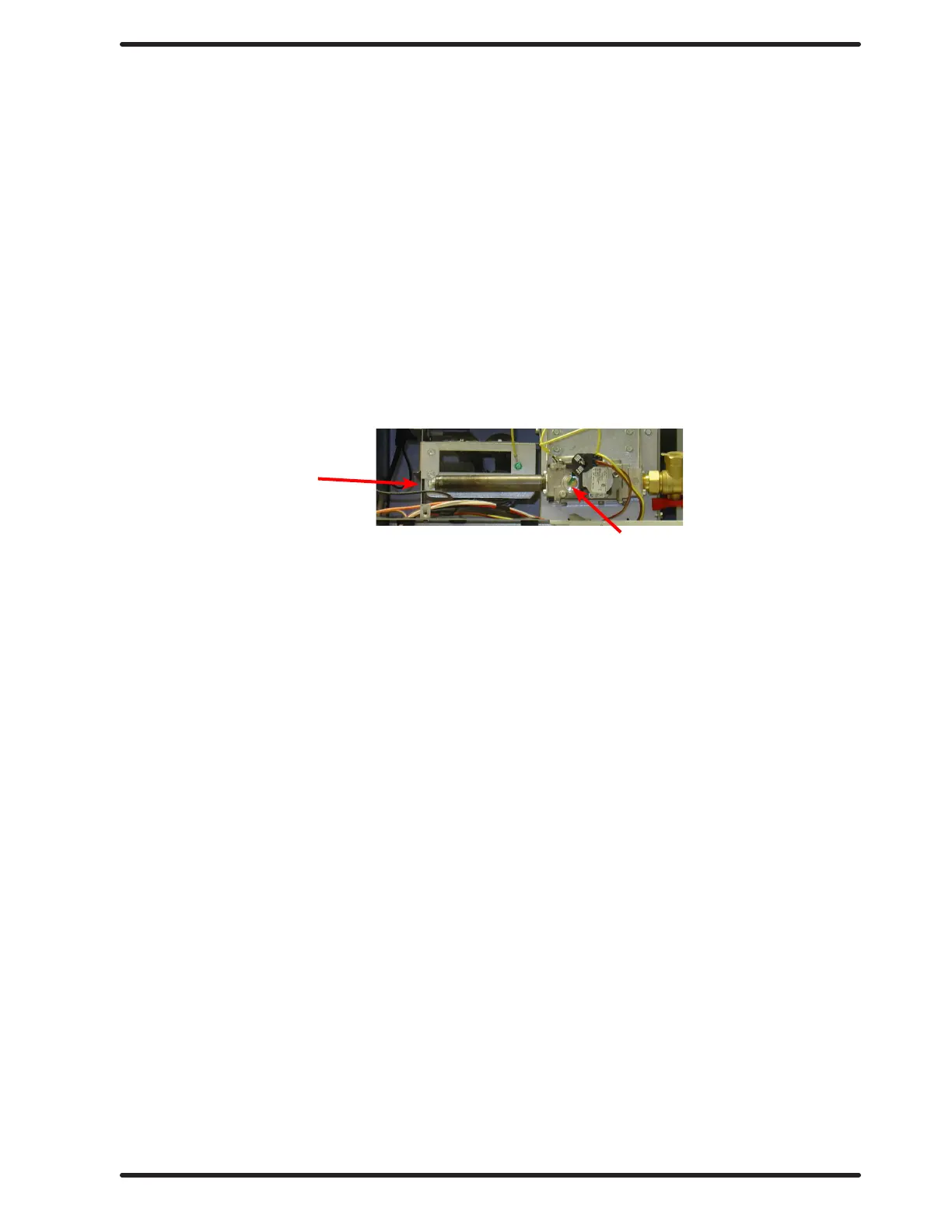
Use the following procedure whenever it is necessary to check the pressure regulator setting.
NOTE: Any adjustment of the pressure regulator must be made with a manometer attached at the plug in
the main burner manifold.
Step 1: Shut o the gas supply to the dryer.
Step 2: Remove the 1/8” pipe plug from the end of the main burner manifold.
Step 3: Attach a manometer to the manifold end.
Step 4: Remove the pressure regulator cover screw on the gas valve.
Step 5: Open the shut-o valve, and operate the dryer.
Step 6: Adjust the pressure for a manometer reading of 3.5” water column gas
pressure. (11.0” for L.P.)
NOTE: The main burners must be operating when adjusting the pressure regulator.
Step 7: Shut o the gas supply to the dryer. Remove the manometer and install the
1/8” pipe plug in the manifold.
Step 8: Open the shut o valve, start the dryer and check for gas leaks while the
burners are ignited.
NOTE: Always remove power from the machine before changing drive belts or working
with the drive and fan system.
Final Drive Belt Replacement
To replace the nal drive belt turn the cylinder slowly by hand and work the belt o of the large
pulley.
Motor Drive Belt Replacement
To replace the motor drive belt the nal drive belt should be removed as above. Next turn the
intermediate drive pulley and work the belt o of it similarly to the above belt.
Blower Motor Removal
Step 1: Remove Rear upper and lower Belt pulley guards.
Step 2: Remove rear electrical box cover.
Step 3: Remove left and bottom side guard.
Step 4: Remove belts.
Step 5: Disconnect wires from the over temperature switch and cut the two wire ties
securing gray wire to motor harness.
Step 6: Remove the wire clamp holding motor wire loom to cross member by
removing the 5/16 screw.
Step 7: Remove the two beaded ties securing harness behind pulleys.
Step 8: Remove last wire tie connecting gray wire to motor harness.
Step 9: Next, inside the rear control box disconnect red wire, ¼ inch quick connect
inside splice connector.
Step 10: Remove black and yellow wires from R1 relay.
Step 11: Remove motor harness from control box.
Step 12: Next remove blower motor, back plate, and impeller from machine by
removing the four 9/16 nuts.
Reassemble in reverse order.
1/8” Pipe Plug
Adjustment Screw Under Plug
Part # 8533-112-001 7/21
 Loading...