50
Blower Impeller Removal
Remove Blower motor assembly. Take notice of the location of the impeller location on the shaft. Remove
the two set screws that hold the motor to the shaft.
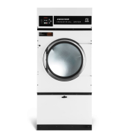
Airow switch removal and adjustment
The air switch assembly is part of the ignition safety circuit and insures that the burner doesn’t operate
unless there is airow. If this doesn’t happen, ignition will not occur. The air switch assembly is located on
the back of the Dryer.
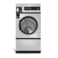
Electronic Ignition Module
This machine uses an electronic spark ignition system to directly light the burners.
Step 1: The electronic ignition module (gray box) is located inside the rear control box.
Step 2: The red wire from the transformer provides 24 VAC through the 1.5 amp fuse
and into the module to operate the entire direct ignition system.
Step 3: The black colored hi-voltage wire (spark plug type) plugs onto the post
connector the module, and the multi-wire plug ts into the side of the module.
Spark Electrode Assembly-Removal
Step 1: Disconnect wires to electrodes.
Step 2: Remove two screws to detach electrode assembly.
NOTE: Proper grounding of the ignition system (yellow wires) is very critical for proper
ignition sequence. If there is no spark or intermittent spark, check black hi-voltage lead wire for damage
or cracks in insulation. This lead wire must not be taped or connected to any metal edges along its length
to prevent pinching and arcing. Also, do not bundle this wire with other wires.
Note : Spark gap and electrode location are important. If the electrode is damaged
or mounting is changed the spark gap may not be correct for ignition to occur. Check for
cracks in the ceramic insulator. Replace electrode assembly if necessary. Also check for
carbon or foreign material on the electrodes and clean if necessary.
Adjustment Screw
Ignition Module
Part # 8533-112-001 7/21
 Loading...