24
NOTE: Always remove power from the machine before changing drive belts or working
with t
he
drive system.
FINAL DRIVE BELT REPLACEMENT
To replace
the
final drive belt turn
the
cylinder slowly
by
hand and work the belt off
of
the large pulley.
MOTOR DRIVE BELT REPLACEMENT
To replace the
motor
drive belt the final drive belt should
be
removed as above.
Cut
the
old motor belt and
remove. The new motor drive
belt fits inside
of
three of the
four
motor mounting bolts. To achieve this,
remove these three
bolts one at a time and slide the belt in past each in turn. In this way the motor is always
supported
by
3 bolts at
any
time.
Note: All drive belts are self adjusting.
TUMBLER
PULLEY REMOVAL
AND
INSTALLATION
Remove the 1 1 /2" nut and lock washer.
Pu
ll the pulley off the shaft. Watch for the locking key on the tumbler
shaft. Upon installation, the tumbler nut should be torqued
to
150
ft./lbs.
INTERMEDIATE PULLEY AND TENSION ARM REMOVAL
1.
The
intermediate pulley
is
retained with a snap ring. Remove the snap ring and the pulley slides
off
the
shaft.
2. With the
pulley off, there is access to the self adjusting tension arm assembly. The tension arm
assembly may
be
removed by removing
the
snap ring that holds it to the tension arm support
assembly pin. The arm assembly is replaced as a complete unit .
3.
The
grease fitting for the intermediate shaft should
be
greased monthly.
TENSION ARM SUPPORT ASSEMBLY ADJUSTMENT
The tension arm support assembly may
be
adjusted
for
alignment
of
the intermediate pulley and also to align
the belts.
The
three outer nuts allow
the
alignment
of
the pin to be adjusted by pivoting the assembly
on
the
center
bolt.
The
center bolt can
be
screwed in
to
allow bringing the complete assembly farther back if neces-
sary
for
belt alignment.
MOTOR AND BLOWER ASSEMBLY REMOVAL AND INSTALLATION
1. Remove
the
tumbler and intermediate pulleys. (see above)
2. Remove the motor wiring
cover
and take the 3 motor wires off.
3. Remove the 9 nuts and
lock washers that retain the blower cover and set assembly out
of
dryer.
4.
The
blower is held
in
place with 2 s
qu
are hea
ded
set screws.
Up
on reassembly, one blower set
screw
should fit in the counter sink in the shaft and the other set screw should go against the flat
side of the shaft. Use red Loctite on the set screws and torque
to
165 in./lbs.
5.
The
motor is mounted with 4 bolts
to
the blower cover.
AIR FLOW SWITCH OPERATION AND ADJUSTMENT
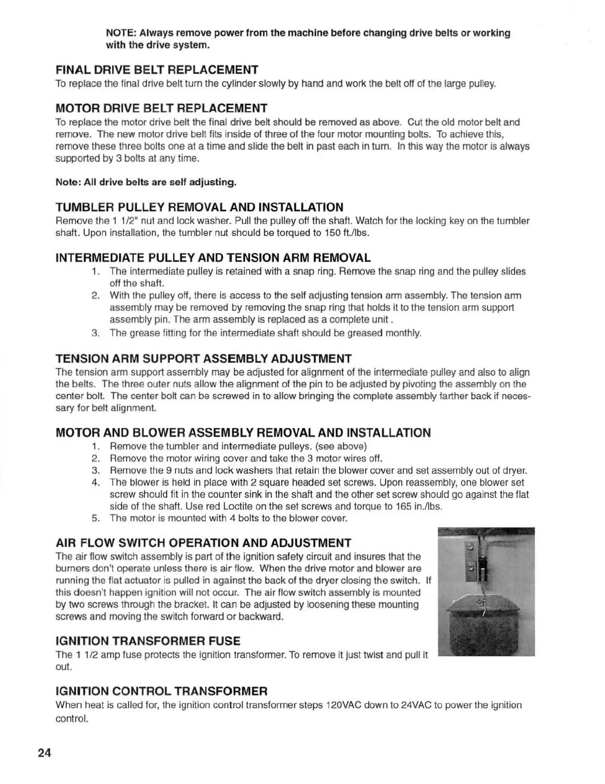
The
ai
r flow switch assembly is part
of
the
ignition safety circuit and insures that the
burners don't operate
unless there
is
air
flow. When the drive motor and blower are
running the
flat actuator is pulled in against the back
of
the dryer closing the switch. If
this
do
es
n't happen ignition will not occur.
The
air
flow switch assembly is mounted
by
two
screws through the bracket. It can
be
adjusted
by
loosening these mounting
sc
rews and moving the switch forward
or
backward.
IGNITION TRANSFORMER FUSE
The 1 1
/2
amp
fuse protects the ignition transformer.
To
remove it just twist and pull
it
out.
IGNITION CONTROL TRANSFORMER
When
heat is called for, the ignition control transformer steps 120VAC down to 24VAC to power the ignition
control.





 To Next Page