
D
Dr. Amy Hodges PhDAug 21, 2025
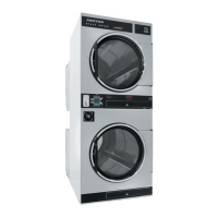
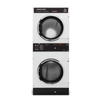
What to do if Dexter Laundry DN20X2 Dryer tumbler does not turn?
- CCandice GlassAug 21, 2025
If your Dexter Laundry Dryer's tumbler isn't turning, begin by inspecting the drive belts and replace them if they are damaged. Next, check the drive motor and its capacitor, replacing them if necessary. Also, examine the door switch contacts and adjustment; adjust or replace the door switch if needed. Finally, determine whether the electronic control is closing the motor relay to power the drive motor. If the motor light on the electronic control is off, replace the control. If the light is on, check the voltage and wiring to the motor.