Intermediate Pulley And Tension Arm Removal
1. The intermediate pulley is retained with a snap ring. Remove the snap ring and the pulley slides
o the shaft.
2. With the pulley o, there is access to the self adjusting tension arm assembly. The tension arm
assembly may be removed by removing the snap ring that holds it to the tension arm support
assembly pin. The arm assembly is replaced as a complete unit.
3. The grease tting for the intermediate shaft should be greased monthly.
Tension Arm Support Assembly Adjustment
The tension arm support assembly may be adjusted for alignment of the intermediate pulley and also
to align the belts. The three outer nuts allow the alignment of the pin to be adjusted by pivoting the
assembly on the center bolt. The center bolt can be screwed in to allow bringing the complete assembly
farther back if necessary for belt alignment.
Motor Blower Assembly Removal And Installation
1. Remove Belts
2. Disconnect Motor harness connector.
3. Remove Tumbler pulley. Remove ¾” bolt, Next remove pulley using “T” bar puller (needed two 3/8”-16
UNC bolts).
4. Remove Idler pulley. Using snap ring pliers, remove snap ring and pulley.
5. Remove Blower back plate (Motor attached). Remove 1 5/16” harness clamp bolt, then remove nine
3/8” nuts and then tilt blower fan to remove.
6. Blower fan is held in place with 2 square headed set screws. Upon reassembly, one blower set screw
should t in the counter sink and the other should mount on the at side of the shaft. Use red locktite
on the set screws and torque to 165 in/lbs.
7. The Motor is mounted with 4 bolts to the motor mounting bracket on the rear of the dryer.
8. Reassemble in reverse order.
Air Flow Switch Operation And Adjustment
The air ow switch assembly is part of the ignition safety circuit and insures that the burners don’t operate
unless there is air ow. When the drive motor and blower are running the at actuator is pulled in against
the back of the dryer closing the switch. If this doesn’t happen ignition will not occur. The air ow switch
assembly is mounted by two screws through the bracket. It can be adjusted by loosening these mounting
screws and moving the switch forward or backward.
Ignition Transformer Fuse
The 1 1/2 amp fuse protects the ignition transformer. To remove it just twist and pull it out.
Ignition Control Transformer
When heat is called for, the ignition control transformer steps 120VAC down to 24VAC to power the ignition
control.
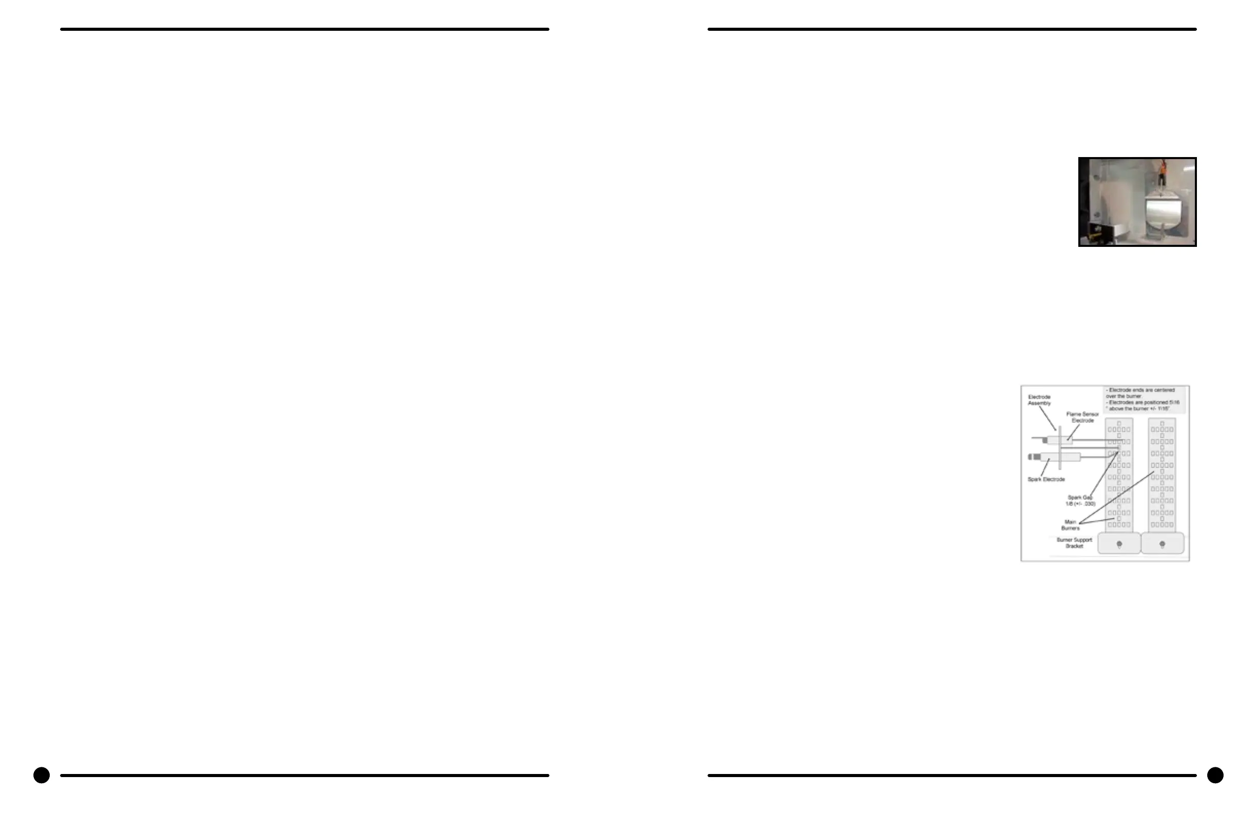
Electronic Ignition Module
This machine uses an electronic spark ignition system to directly light the burners in each tumbler.
1. The electronic ignition module for each tumbler is located inside the electrical box. This is the
metal box on the back of each tumbler area directly to the right of the nal drive pulleys.
2. The red wire from the transformer traveling thru the 1.5 amp fuse and into the module supplies
the 24VAC required to operate the entire direct ignition system.
3. The black colored hi-voltage wire (spark plug type) plugs onto the post connector on the module,
and the multi-wire plug ts into the side of the module.
Spark Ignition Module Removal
If the ignition modules are mounted on a bracket, see section A. Otherwise, see section B.
A: With mounting bracket
Remove the connector housing of the wiring harness attached to the ignition module. Then,
remove the terminal of the hi-voltage cable attached to the ignition
module. Next, remove the mounting screws holding the ignition module
mounting bracket in the rear control box. Lastly, remove the nuts
holding the ignition module on its mounting bracket.
B: Without mounting bracket
Remove all of the terminals of the wiring harness attached to the
ignition module. Then, remove the terminal of the hi-voltage cable
attached to the ignition module. Lastly, remove the mounting screws holding the ignition module
in the control box. If there is no spark or intermittent spark, check black hi-voltage lead wire for
damage
NOTE: Proper grounding of the ignition system (yellow wires) is very critical for
proper ignition sequence.
Ignition System-Function & Sequence
During normal dryer operation, the following occurs:
1. The dryer electronic control calls for heat.
2. If the drive motor is running, the motor safety circuit
provides power to the electronic control. If the control
senses that the heat should be on, a circuit is closed
allowing power through the high limit thermostat and air
ow switch to the ignition transformer. The transformer
provides 24VAC to the ignition module and sparking
occurs at the ignition electrode. At the same time 24VAC
is applied to the gas valve.
3. Once the ame is established, the sensing electrode
detects the presence of ame and the sparking stops.
4. If for any reason the ame is not established in a
period of 10 seconds, the electronic control will try this
sequence for 3 tries. Normally the 10 seconds “Trial For Ignition” period is ample to establish and
prove ame.
5. If the ame is shutdown or blown out during operation, the ignitor will imm.ediately go into “Trial
For Ignition” again for 10 seconds.
6. However,at the end of 3 separate retries of 10 seconds “Trial for Ignition”, the ame is not
established, the ignition system goes into “Safety Lock-Out” and will not reactivate the “Trial for
Ignition” until there is a current interruption for a period of 15 seconds. This interruption can be
provided by opening the dryer loading door and allowing the machine to come to a complete stop
for 15 seconds.
50 51
Part # 8533-108-001 10/22 Part # 8533-108-001 10/22
Electric Heated
Parts Data