Do you have a question about the Deye SUN-50K-SG01HP3-EU-BM4 and is the answer not in the manual?
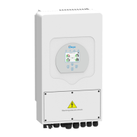
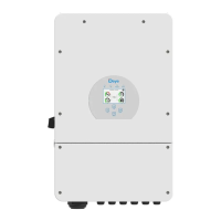
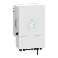
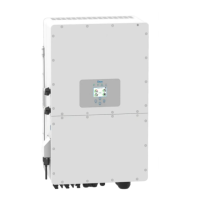
Details the physical layout and components of the hybrid inverter, including indicators and ports.
Provides dimensional drawings and specifications for the inverter and its mounting bracket.
Lists the key technical capabilities and functionalities of the hybrid inverter.
Illustrates a typical system setup with PV, battery, load, grid, and generator.
Itemizes all components included in the inverter package for installation.
Covers installation precautions, site selection criteria, and general mounting guidelines.
Details the procedure and safety requirements for connecting the battery system to the inverter.
Explains the purpose and pin assignments for various communication and control ports.
Provides instructions and specifications for connecting the inverter to the grid and backup load.
Outlines the requirements and safety precautions for connecting the photovoltaic modules.
Illustrates the wiring diagram for connecting Current Transformers (CTs) for power monitoring.
Shows wiring diagrams for connecting CHNT and Eastron energy meters to the inverter.
Details the mandatory procedure for connecting the inverter's ground cable to the earth.
Briefly mentions Wi-Fi plug configuration as an optional feature.
Provides a general wiring diagram for inverter application connecting PV, battery, load, grid, and generator.
Presents wiring diagrams for applications with neutral separated from PE and backup functions.
Illustrates a typical system setup integrating a diesel generator with the hybrid inverter.
Shows how to connect multiple inverters in a three-phase parallel configuration.
Explains the procedure for turning the inverter unit on and off.
Describes the inverter's front panel indicators, function keys, and LCD display.
Details the information presented on the inverter's main LCD screen and its interactive elements.
Visualizes the navigation path through the inverter's LCD menu options.
Explains how to view and interpret daily, monthly, and yearly solar power generation data.
Shows graphical representations of solar, load, and grid power over different time periods.
Covers settings for time synchronization, display dimming, and factory reset password.
Displays generator output information and allows Lithium battery mode configuration.
Adjusts output power based on grid frequency deviations and protection limits.
Configures active and reactive power output based on grid voltage variations.
Sets reactive power and power factor based on active power output.
Configures Low Voltage Ride-Through (LVRT) parameters, noted as reserved.
Illustrates a basic system setup with PV and battery.
Illustrates a system setup including a generator connection.
Illustrates a system setup incorporating a smart load feature.
Illustrates a system setup for AC coupling with an on-grid inverter.
Details the pin configuration for the RJ45 port on BMS1.
Details the pin configuration for the RJ45 port on BMS2.
Details the pin configuration for the RJ45 port used for meter connection.
Details the pin configuration for the RS485 port.
Details the pin configuration for the RS232 port used for Wi-Fi datalogger.