www.dfi .com
32
Chapter 2 Hardware Installation
Chapter 2
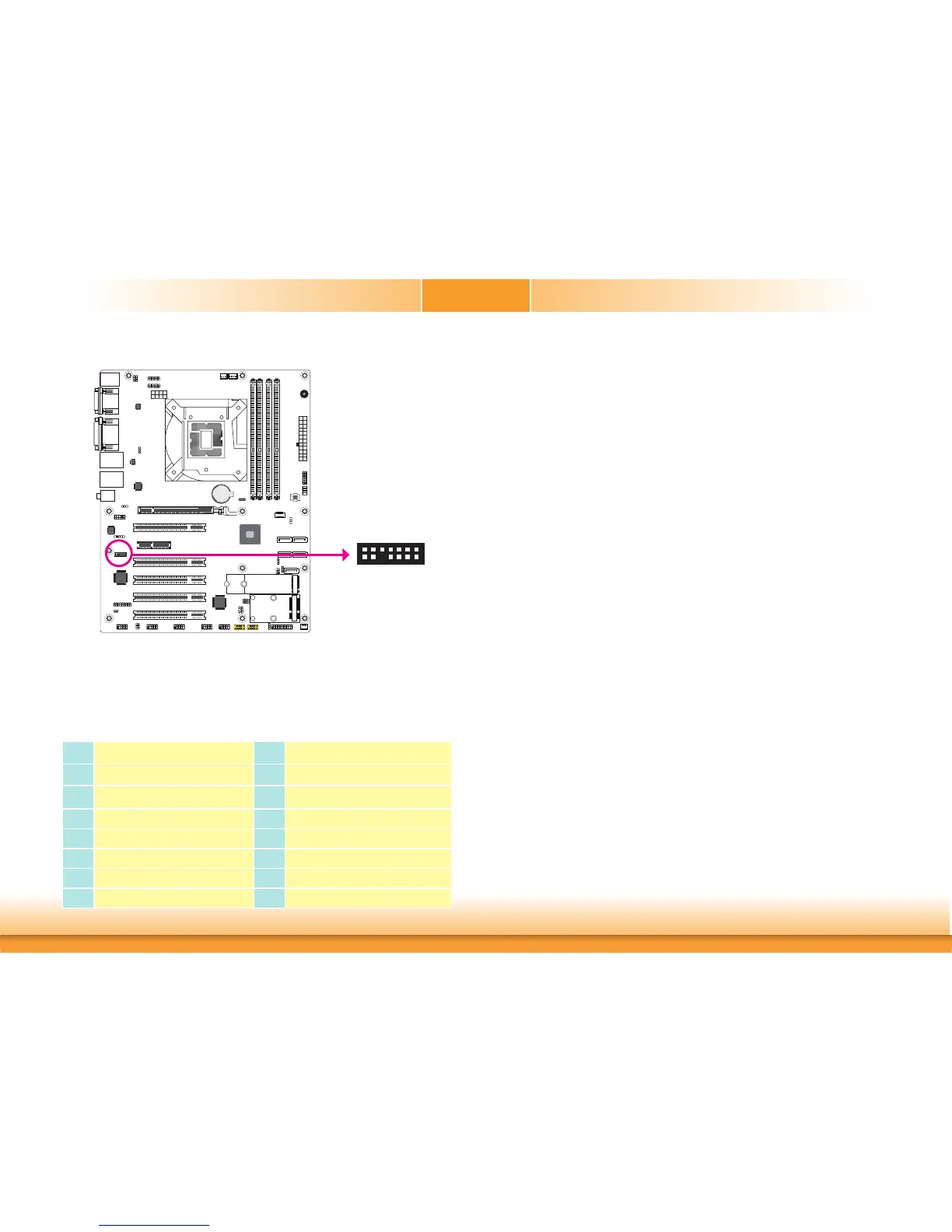
LPC Connector
LPC
2
1
14
13
The Low Pin Count Interface was defined by Intel
®
Corporation to facilitate the industry’s tran-
sition towards legacy free systems. It allows the integration of low-bandwidth legacy I/O com-
ponents within the system, which are typically provided by a Super I/O controller. Furthermore,
it can be used to interface firmware hubs, Trusted Platform Module (TPM) devices and embed-
ded controller solutions. Data transfer on the LPC bus is implemented over a 4 bit serialized
data interface, which uses a 33MHz LPC bus clock. For more information about LPC bus refer
to the Intel
®
Low Pin Count Interface Specification Revision 1.1’. The table below indicates the
pin functions of the LPC connector.
Pin Pin Assignment Pin Pin Assignment
1
L_CLK
2
L_AD1
3
L_RST#
4
L_AD0
5
L_FRAME#
6
3V3
7
L_AD3
8
GND
9
L_AD2
10
---
11
INT_SERIRQ
12
GND
13
5VSB
14
5V
A61
Battery
A61