25
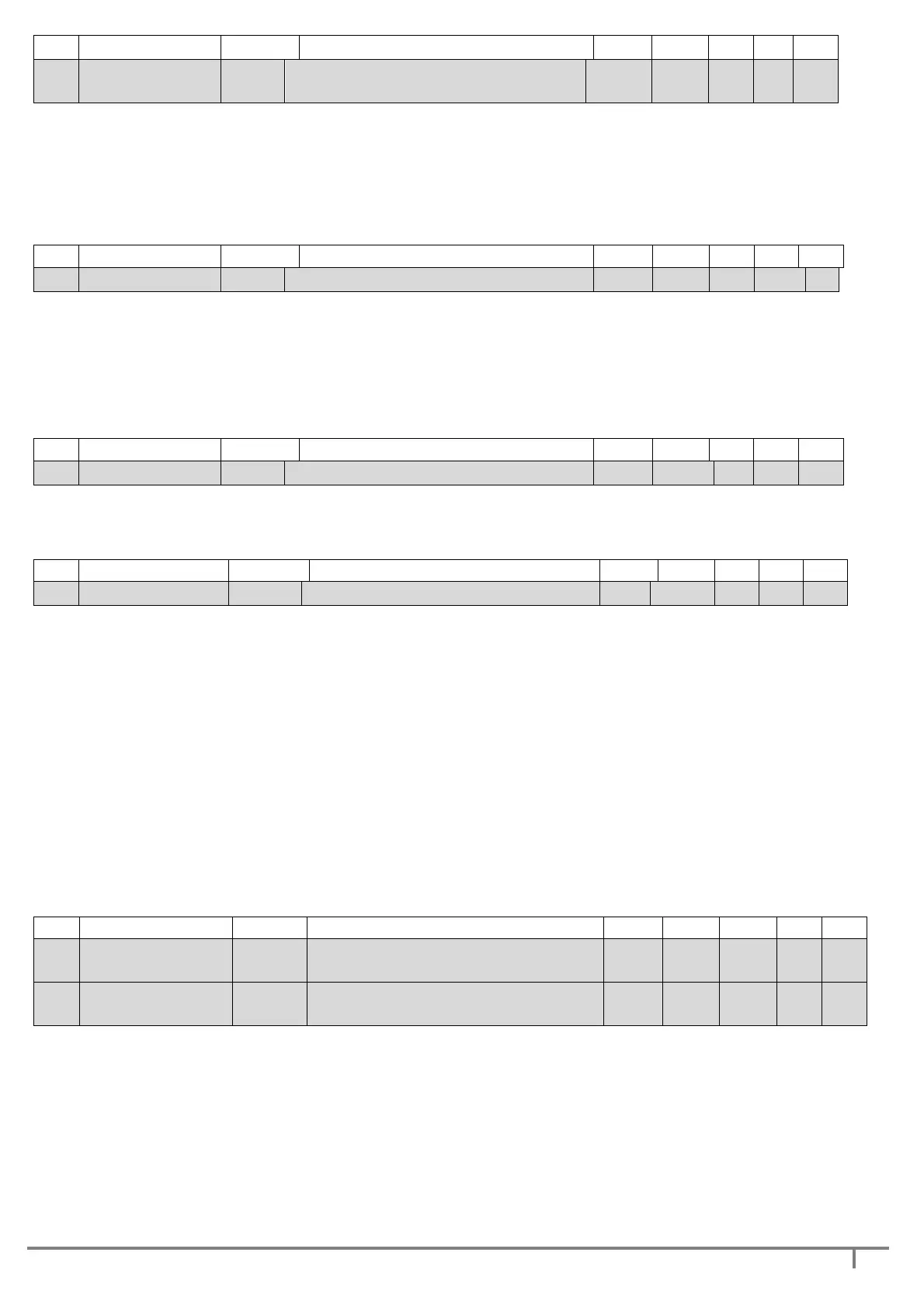
PARAMETER SYMBOL SHORT DESCRIPTION UNIT default
min Max
step
2.14
FACTOR
RF Inverter reactivity factor - 2 1 5 1
The reactivity factor indicates the DGBOX response velocity, to return to set pressure, compared to
pressure variations in the plant due to linked-unit withdrawal.
The values that can be selected go from 1 (slow reaction, suitable for large-inertia plants or with
possible resonance phenomena) to 5 (very fast reaction, suitable in case of fast changes in system
pressure).
2.15
SWITCH FREQ SF Inverter switching frequency kHz 8 4 12 2
The parameter defines the switch-over frequency of the inverter used to produce the waveform which
will supply the motor. The switching frequency can be selected between 4 kHz and 12 kHz.
This frequency, in the absence of a sinusoid electronic filter on the cable coming out of the motor, must
be reduced together with any increase in the length of the cable itself.
NOTE The length of the cable must not in any case exceed 10 m without the use of a sinusoid filter.
2.16
PRESSURE UNIT PU Pressure unit of measure - bar PSI
bar -
The parameter permits selecting the unit of measurement of the pressure displayed on the display
screen (bar or psi).
2.17
ACCELERATION ACC Speed of variation of frequency Hz/s 20 10 40 1
The parameter regulates the speed of variation of the inverter frequency and consequently the speed at
which the pump switches to the required speed.
Acceleration is represented in Hz/s (Hz per second) and indicates by how many Hz the speed of rotation
of the pump varies within the unit of time.
example: ACCELERATION = 25
the parameter indicates a pump acceleration of 25 Hz per second. It follows that, starting with a state of
pump stopped, it will take 2s to reach the speed of 50 Hz.
This parameter, if regulated at minimum (10Hz/s) permits starting pumps with large inertia (PD
2
)
without excessive current absorption at breakaway.
NOTE. The parameter ACC is automatically changed when regulating the RF parameter (see parameter
2.7 RESPONSE FACTOR); such operation is performed to adapt acceleration to device response
requirements.
2.18
OFF FREQ. SP1 OF1
off frequency with working
pressure 1
Hz 40 Fmin
**
45 0.1
2.19
OFF FREQ. SP2 OF2
off frequency with working
pressure 2
Hz 40 Fmin
**
45 0.1
This parameter must be set only with operation without flow sensor (see - FLOW SENSOR parameter
3.13).
The parameter defines the frequency below which it is considered there is no more flow request and
therefore, after a time defined by the FLOW TIMEOUT parameter (see parameter 2.6 FLOW TIMEOUT)
the pump must be stopped.
the frequency below which it is considered there is no more flow request (switch-off frequency)
depends on the selected work pressure.


 To Next Page