Page 25
The Outputs screen has three tabs:
1. Label
You can modify an output name by:
a) Select an output and select its label.
b) Enter the new preset name and select the OK button.
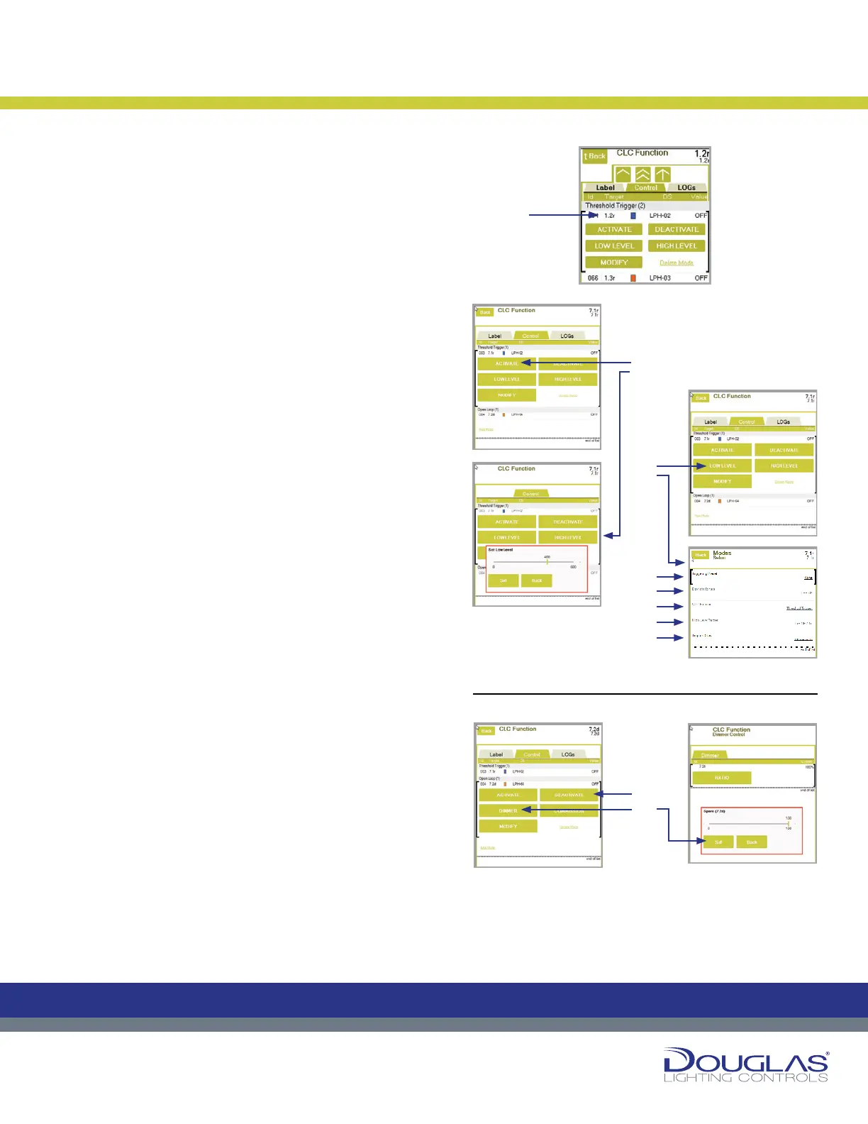
2. Control
You can activate, deactivate, or congure a selected output. The
procedures differ depending on the CLC setting type, as follows:
Threshold Trigger
a) Activate or deactivate an output by selecting the ACTIVATE
or DEACTIVATE button.
An orange rectangle is displayed for activated modes and a
blue rectangle for deactivated modes.
b) Select the LOW LEVEL or HIGH LEVEL button to view
the current Low Level Set Point or High Level Set Point,
respectively. Adjust the set points by using the slider and
selecting the Set button.
c) Select the MODIFY button to view or modify sensor
parameters, as follows:
1. Triggering Preset - display any of the CLC triggering
presets associated with the output.
2. Daylight Sensor - select the associated link to modify
the controlling sensor. Next, select the new sensor.
3. CLC Function - select the associated link to modify the
CLC type. Next, select the Open Loop or Closed Loop
option and select the OK button.
4. High Level Target - select the associated link to modify
the high level target, which is the relay output that is
turned on when the light levels exceed the High Level
Set Point. Next, select the new output.
5. Test Mode - select the associated link to enable or
disable the test mode. By default, this option is turned
off. If this option is enabled, there is no delay time
between light level readings.
Open Loop
a) Activate or deactivate an output by selecting the ACTIVATE
or DEACTIVATE button.
An orange rectangle is displayed for activated modes and a
blue rectangle for deactivated modes.
b) Select the DIMMER button to adjust the dimmer out dimming
level Set Point. This is set as a percentage. Use the slider to
adjust the level and select the Set button. In the case when
the there are multiple dimmer outputs controlled by the same
sensor, this value is the dimmer RATIO.
Constant Lighting Controller
24
Dialog® Lighting Control System
The Outputs screen has three tabs:
1. Label
You can modify an output name by:
a) Select an output and select its label.
b) Enter the new preset name and select the OK button.
2. Control
Y
ou can activate, deactivate, or congure a selected output. The
procedures dier depending on the CLC setting type, as follows:
Threshold Trigger
a) Activate or deactivate an output by selecting the ACTIVATE or
DEACTIVATE button.
An orange rectangle is displayed for activated modes and a blue
rectangle for deactivated modes.
b) Select the LOW LEVEL or HIGH LEVEL button to view the current
Low Level Set Point or High Level Set Point, respectively. Adjust
the set points by using the slider and selecting the Set button.
c) Select the MODIFY button to view or modify sensor parameters, as
follows:
1. Triggering Preset - display any of the CLC triggering presets
associated with the output.
2. Daylight Sensor - select the associated link to modify the
controlling sensor. Next, select the new sensor.
3. CLC Function - select the associated link to modify the CLC type.
Next, select the Open Loop or Closed Loop option and select the
OK button.
4. High Level Target - select the associated link to modify the high
level target, which is the relay output that is turned on when
the light levels exceed the High Level Set Point. Next, select
the new output.
5. Test Mode - select the associated link to enable or disable the test
mode. By default, this option is turned o. If this option is enabled,
there is no delay time between light level readings.
Open Loop
a) Activate or deactivate an output by selecting the
ACTIVATE or DEACTIVATE button.
An orange rectangle is displayed for activated modes and
a blue rectangle for deactivated modes.
b) Select the DIMMER button to adjust the dimmer
out dimming level Set Point. This is set as a percentage.
Use the slider to adjust the level and select the
Set button. In the case when the there are multiple
dimmer outputs controlled by the
same sensor, this value is the dimmer RATIO.
Constant Lighting Controller
C
M
Y
CM
MY
CY
CMY
K
24
Dialog® Lighting Control System
The Outputs screen has three tabs:
1. Label
You can modify an output name by:
a) Select an output and select its label.
b) Enter the new preset name and select the OK button.
2. Control
Y
ou can activate, deactivate, or congure a selected output. The
procedures dier depending on the CLC setting type, as follows:
Threshold Trigger
a)
Activate or deactivate an output by selecting the ACTIVATE or
DEACTIVATE button.
An orange rectangle is displayed for activated modes and a blue
rectangle for deactivated modes.
b) Select the LOW LEVEL or HIGH LEVEL button to view the current
Low Level Set Point or High Level Set Point, respectively. Adjust
the set points by using the slider and selecting the Set button.
c) Select the MODIFY button to view or modify sensor parameters, as
follows:
1. Triggering Preset - display any of the CLC triggering presets
associated with the output.
2. Daylight Sensor - select the associated link to modify the
controlling sensor. Next, select the new sensor.
3. CLC Function - select the associated link to modify the CLC type.
Next, select the Open Loop or Closed Loop option and select the
OK button.
4. High Level Target
- select the associated link to modify the high
level target, which is the relay output that is turned on when
the light levels exceed the High Level Set Point. Next, select
the new output.
5. Test Mode - selec
t the associated link to enable or disable the test
mode. By default, this option is turned o. If this option is enabled,
there is no delay time between light level readings.
Open Loop
a)
Activate or deactivate an output by selecting the
ACTIVATE or DEACTIVATE button.
An orange rectangle is displayed for activated modes and
a blue rectangle for deactivated modes.
b) Select the DIMMER button to adjust the dimmer
out dimming level Set Point. This is set as a percentage.
Use the slider to adjust the level and select the
Set button. In the case when the there are multiple
dimmer outputs controlled by the
same sensor, this value is the dimmer RATIO.
Constant Lighting Controller
C
M
Y
CM
MY
CY
CMY
K
24
Dialog® Lighting Control System
The Outputs screen has three tabs:
1. Label
You can modify an output name by:
a) Select an output and select its label.
b) Enter the new preset name and select the OK button.
2. Control
You can activate, deactivate, or congure a selected output. The
procedures dier depending on the CLC setting type, as follows:
Threshold Trigger
a) Activate or deactivate an output by selecting the ACTIVATE or
DEACTIVATE button.
An orange rectangle is displayed for activated modes and a blue
rectangle for deactivated modes.
b) Select the LOW LEVEL or HIGH LEVEL button to view the current
Low Level Set Point or High Level Set Point, respectively. Adjust
the set points by using the slider and selecting the Set button.
c) Select the MODIFY button to view or modify sensor parameters, as
follows:
1. Triggering Preset - display any of the CLC triggering presets
associated with the output.
2. Daylight Sensor - select the associated link to modify the
controlling sensor. Next, select the new sensor.
3. CLC Function - select the associated link to modify the CLC type.
Next, select the Open Loop or Closed Loop option and select the
OK button.
4. High Level Target - select the associated link to modify the high
level target, which is the relay output that is turned on when
the light levels exceed the High Level Set Point. Next, select
the new output.
5. Test Mode - select the associated link to enable or disable the test
mode. By default, this option is turned o. If this option is enabled,
there is no delay time between light level readings.
Open Loop
a) Activate or deactivate an output by selecting the
ACTIVATE or DEACTIVATE button.
An orange rectangle is displayed for activated modes and
a blue rectangle for deactivated modes.
b) Select the DIMMER button to adjust the dimmer
out dimming level Set Point. This is set as a percentage.
Use the slider to adjust the level and select the
Set button. In the case when the there are multiple
dimmer outputs controlled by the
same sensor, this value is the dimmer RATIO.
Constant Lighting Controller
C
M
Y
CM
MY
CY
CMY
K
24
Dialog® Lighting Control System
The Outputs screen has three tabs:
1. Label
You can modify an output name by:
a) Select an output and select its label.
b) Enter the new preset name and select the OK button.
2. Control
You can activate, deactivate, or congure a selected output. The
procedures dier depending on the CLC setting type, as follows:
Threshold Trigger
a) Activate or deactivate an output by selecting the ACTIVATE or
DEACTIVATE button.
An orange rectangle is displayed for activated modes and a blue
rectangle for deactivated modes.
b) Select the LOW LEVEL or HIGH LEVEL button to view the current
Low Level Set Point or High Level Set Point, respectively. Adjust
the set points by using the slider and selecting the Set button.
c) Select the MODIFY button to view or modify sensor parameters, as
follows:
1. Triggering Preset - display any of the CLC triggering presets
associated with the output.
2. Daylight Sensor - select the associated link to modify the
controlling sensor. Next, select the new sensor.
3. CLC Function - select the associated link to modify the CLC type.
Next, select the Open Loop or Closed Loop option and select the
OK button.
4. High Level Target - select the associated link to modify the high
level target, which is the relay output that is turned on when
the light levels exceed the High Level Set Point. Next, select
the new output.
5. Test Mode - select the associated link to enable or disable the test
mode. By default, this option is turned o. If this option is enabled,
there is no delay time between light level readings.
Open Loop
a) Activate or deactivate an output by selecting the
ACTIVATE or DEACTIVATE button.
An orange rectangle is displayed for activated modes and
a blue rectangle for deactivated modes.
b) Select the DIMMER button to adjust the dimmer
out dimming level Set Point. This is set as a percentage.
Use the slider to adjust the level and select the
Set button. In the case when the there are multiple
dimmer outputs controlled by the
same sensor, this value is the dimmer RATIO.
Constant Lighting Controller
C
M
Y
CM
MY
CY
CMY
K
a)
1.
a)
b)
2.
3.
4.
5.
b)
c)
Threshold Trigger
Open Loop:
 Loading...