Page 5
Outputs
Output Menu
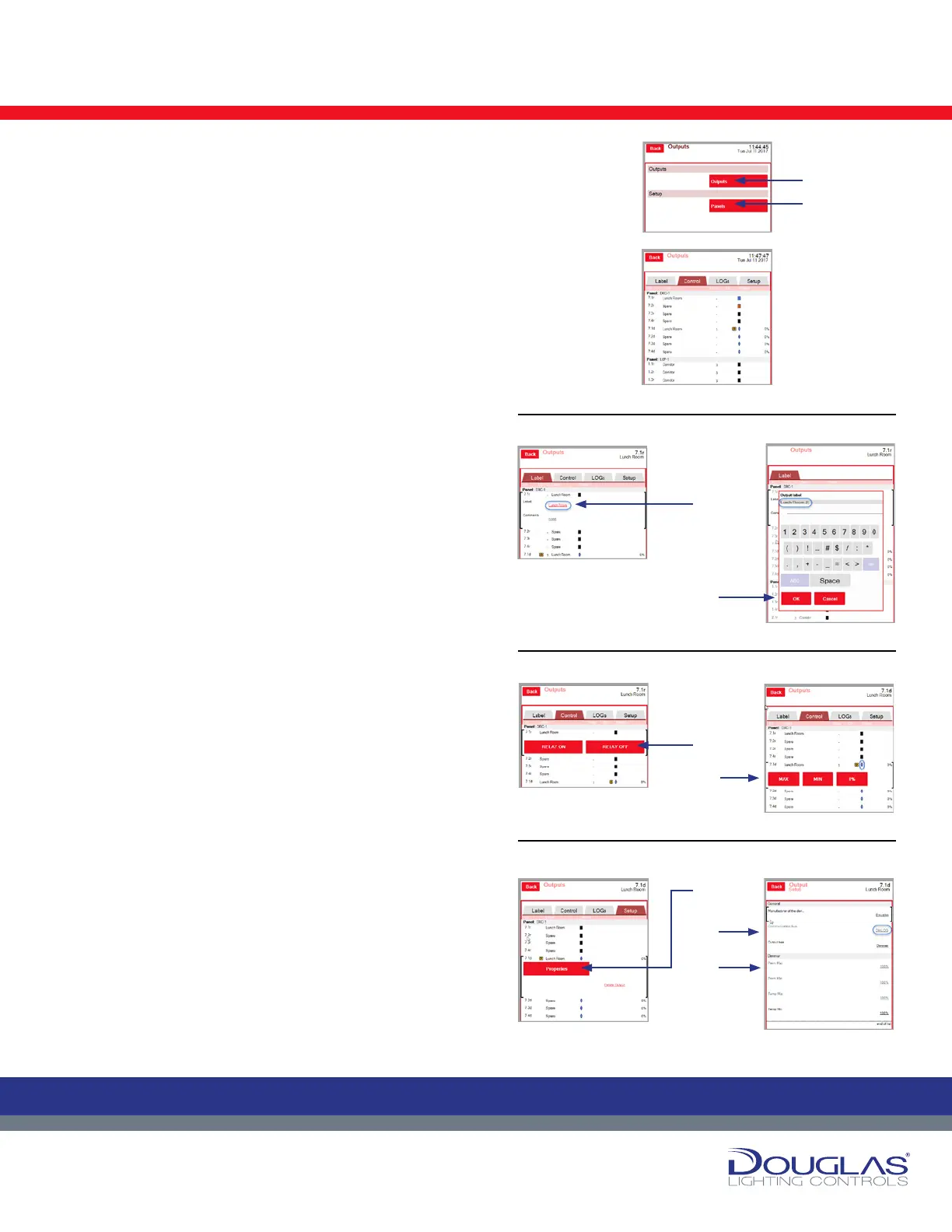
Output menu has two submenus—Outputs and Setup:
1. Outputs
2. Panels
1. Outputs > Outputs
The Outputs screen displays the properties for each panel. The
following describes each column:
id - address, channel (r indicates a relay and d indicates a
dimmer)
Label - descriptive name, which is assigned in this submenu
group
Group - group the panel is assigned to
DS - daylight sensor status (if applicable)
Status - color indicates the status of the panel (blue is ON,
orange is OFF, Black is not connected)
The Outputs screen has four tabs:
1. Label
To modify a label name:
a) Select a panel and click on its label.
b) Enter the new label name and click the OK button.
2. Control
To override the control settings:
a) Turn a relay on or off by selecting the RELAY ON or RELAY
OFF button.
b) Adjust the dimmer levels to a maximum or minimum level by
selecting the corresponding button or setting a percentage
of brightness by using the slider.
3. LOGs
You can view the historical activity for a selected output by
selecting the LOGs tab.
4. Setup
a) Select an output and select the Properties button.
b) Select the communication bus you are conguring. The
default communication bus is Dialog.
c) Select the output type—Relay or Dimmer. If the selected
output type is a dimmer, you can adjust the brightness by
using the slider.
5
Dialog® Lighting Control System
Outputs
The Outputs screen has four tabs:
1. Label
To modify a label name:
a) Select a panel and click on its label.
b) Enter the new label name and click the OK button.
2. Control
To override the control settings:
a) Turn a relay on or off by selecting the RELAY ON
or RELAY OFF button.
b) Adjust the dimmer levels to a maximum or
minimum level by selecting the corresponding
button or setting a percentage of brightness by
using the slider.
3. LOGs
You can view the historical activity for a selected output
by selecting the LOGs tab.
4. Setup
a) Select an output and select the Properties button.
b) Select the communication bus you are configuring.
The default communication bus is Dialog.
c) Select the output type—Relay or Dimmer. If the
selected output type is a dimmer, you can adjust the
brightness by using the slider.
Output Menu
The Output menu has two submenus—Outputs and Setup:
1. Outputs
2. Panels
1. Outputs > Outputs
The Outputs screen displays the properties for each panel. The
following describes each column:
id - address, channel (r indicates a relay and d indicates a dimmer)
Label - descriptive name, which is assigned in this submenu group
Group - group the panel is assigned to
DS - daylight sensor status (if applicable)
Status - color indicates the status of the panel (blue is ON, orange is
OFF, Black is not connected)
1.
2.
a)
a)a)
a)
b)
b)
c)
b)
Outputs
1. Label
4. Setup
2. Control
 Loading...