Page 27
2. Control (continued)
Closed Loop
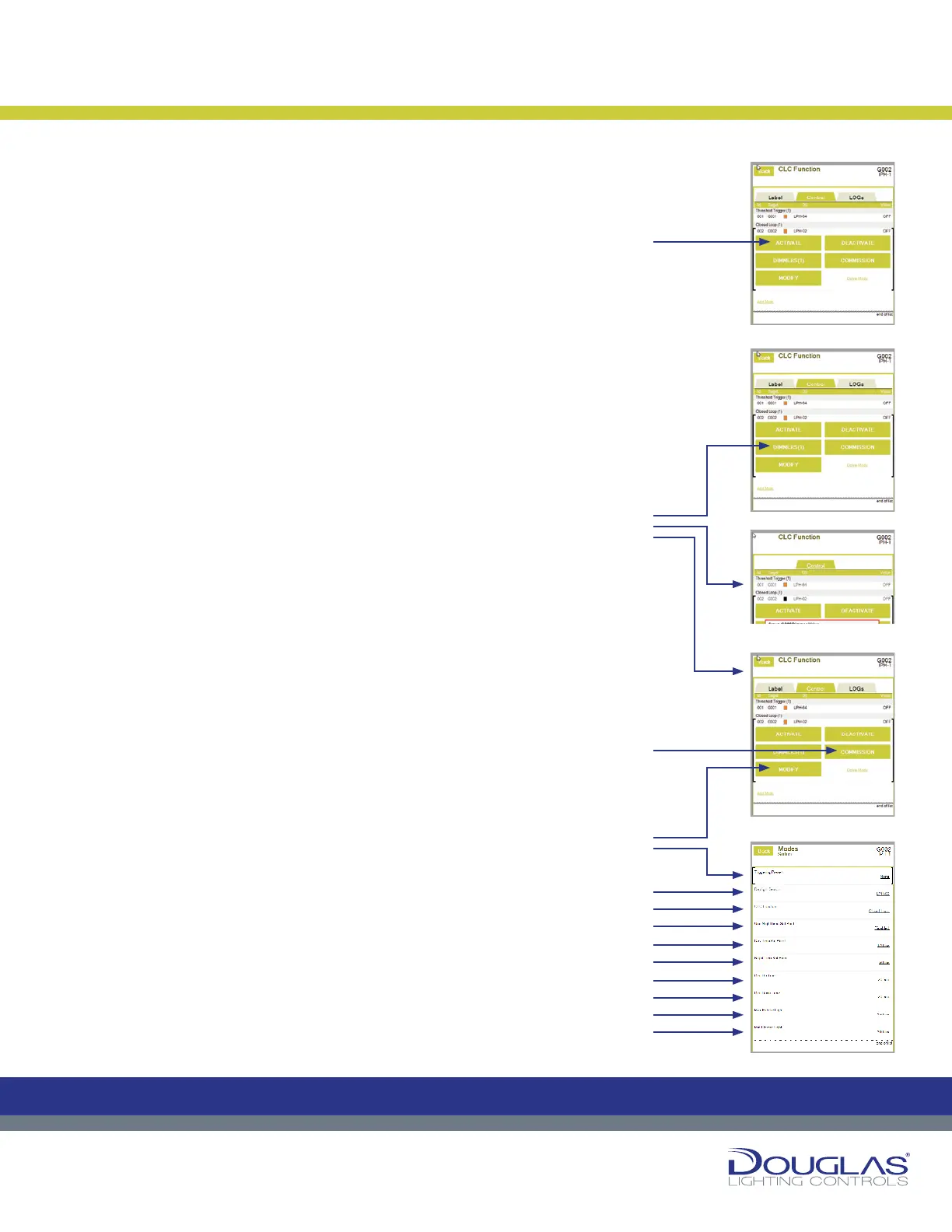
a) Activate or deactivate an output by selecting the ACTIVATE or
DEACTIVATE button.
An orange rectangle is displayed for activated modes and a blue
rectangle for deactivated modes.
b) Select the DIMMERS button to adjust the dimmer out dimming level Set
Point. This is set as a percentage. Use the slider to adjust the level and
select the Set button. In the case when the there are multiple dimmer
outputs controlled by the same sensor, this value is the dimmer RATIO.
c) Select the COMMISSION button to initiate the Commissioning rocess, in
which the system tests the full dimming spectrum and sets up the Open
Loop CLC. Commissioning is a multi-step process and this is typically
done as part of the initial installation. This must be done correctly for the
CLC mode to function properly. If you are initiating a Commission, refer to
the documentation describing the commissioning procedure.
d) Select the MODIFY button to view or modify the sensor parameters, as
follows:
1. Triggering Preset - display any of the CLC triggering presets
associated with the output.
2. Daylight Sensor - select the associated link to modify the controlling
sensor. Next, select the new sensor.
3. CLC Function - select the associated link to modify the CLC type.
Next, select the Open Loop or Closed Loop option and select the
OK button.
4. Day Time Set Point - select the associated link to modify the value,
which is used in the commissioning process. First, select the Interior
or Exterior option, use the slider to set the new value, and select the
OK button.
5. Night Time Set Point - select the associated link to modify the value,
which is used in the commissioning process. Use the slider to set the
new value and select the OK button.
6. Dim Up Time - select the associated link to modify the value, which
is the maximum time required for the dimmer to go from a lower to a
higher dimming percentage when the ambient brightness changes.
Use the slider to set the new value and select the OK button.
7. Dim Down Time - select the associated link to modify the value, which
is the maximum time required for the dimmer to go from a higher to
a lower dimming percentage when the ambient brightness changes.
Use the slider to set the new value and select the OK button.
8. Max Electric Light - select the associated link to modify the value,
which is the brightness stable light level value in the area controlled
by the CLC. Use the slider to set the new value and select the OK
button.
9. Min Electric Light - select the associated link to modify the value,
which is the dimmest stable light level value in the area controlled by
the CLC. Use the slider to set the new value and select the OK button.
3. LOGs
You can view the historical activity for a selected mode by selecting the LOGs
tab.
Constant Lighting Controller
26
Dialog® Lighting Control System
2. Control (continued)
Closed Loop
a) Activate or deactivate an output by selecting the ACTIVATE or
DEACTIVATE button.
An orange rectangle is displayed for activated modes and a blue rectangle
for deactivated modes.
b) Select the DIMMERS button to adjust the dimmer out dimming level Set
Point. This is set as a percentage. Use the slider to adjust the level and
select the Set button. In the case when the there are multiple dimmer
outputs controlled by the same sensor, this value is the dimmer RATIO.
c) Select the COMMISSION button to initiate the Commissioning process,
in which the system tests the full dimming spectrum and sets up the
Open Loop CLC. Commissioning is a multi-step process and this is
typically done as part of the initial installation. This must be done correctly
for the CLC mode to function properly. If you are initiating a Commission,
refer to the documentation describing the commissioning procedure.
d) Select the MODIFY button to view or modify the sensor parameters, as
follows:
1. Triggering Preset - display any of the CLC triggering presets
associated with the output.
2. Daylight Sensor - select the associated link to modify the controlling
sensor. Next, select the new sensor.
3. CLC Function - select the associated link to modify the CLC type. Next,
select the Open Loop or Closed Loop option and select the OK button.
4. Day Time Set Point - select the associated link to modify the value,
which is used in the commissioning process. First, select the Interior
or Exterior option, use the slider to set the new value, and select the OK
button.
5. Night Time Set Point - select the associated link to modify the value,
which is used in the commissioning process. Use the slider to set the
new value and select the OK button.
6. Dim Up Time - select the associated link to modify the value, which is
the maximum time required for the dimmer to go from a lower to a higher
dimming percentage when the ambient brightness changes. Use the
slider to set the new value and select the OK button.
7. Dim Down Time - select the associated link to modify the value, which
is the maximum time required for the dimmer to go from a higher to a
lower dimming percentage when the ambient brightness changes. Use
the slider to set the new value and select the OK button.
8. Max Electric Light - select the associated link to modify the value,
which is the brightness stable light level value in the area controlled by
the CLC. Use the slider to set the new value and select the OK button.
9. Min Electric Light - select the associated link to modify the value, which
is the dimmest stable light level value in the area controlled by the CLC.
Use the slider to set the new value and select the OK button.
3. LOGs
You can view the historical activity for a selected mode by selecting the LOGs
tab.
Constant Lighting Controller
C
M
Y
CM
MY
CY
CMY
K
Control:
a)
1.
2.
3.
4.
5.
6.
7.
8.
9.
c)
b)
d)
 Loading...