7
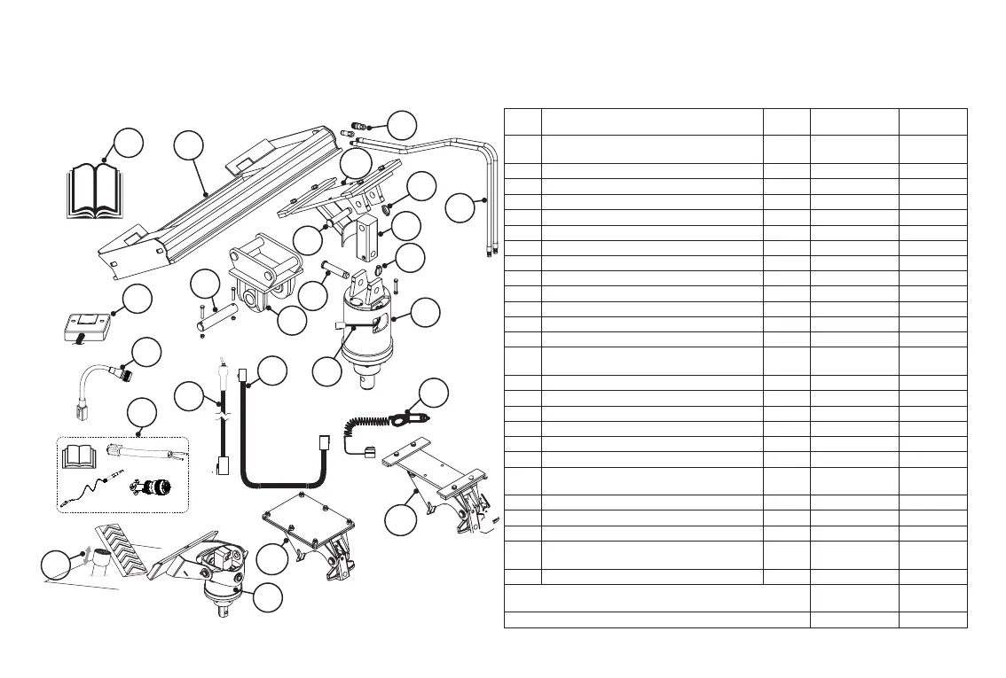
To avoid any inconvenience before operation, please check that you have received the following items which you
may have ordered. Items may dier depending on type of machine on which the drive units are to be tted to.
REF DESCRIPTION QTY
SINGLE
SPEED
2-SPD
12V/24V
A
Standard drive unit - or - Swing control sys-
tem drive unit - or - Halo (see chapter 17)
1 • •
B Quick release couplers. Set • •
C Hydraulic hose kit. Set • •
D Lynch pin (clip) or bolt. 1 • •
E Linkage suit standard drive unit. 1 • •
K PIN (Standard drive unit - to - linkage). 1 • •
L Digga motor control harness (3M). 1 N/A •
M Extension harness 3M/6M/12M/15M. 1 N/A Optional
N 2 Speed controller. 1 N/A Optional
O Remote toggle switch. 1 N/A Optional
P Remote oor mounted switch. 1 N/A Optional
Q 12V/24V Power lead. 1 N/A Optional
R Operator’s manual. 1 • •
REF FOR SKID STEER LOADERS QTY SINGLE SPEED
2-SPD
12V/24V
G Slide frame. 1 • •
J Pin (Cradle - to - linkage). 1 • •
F-1 Standard slide cradle. 1 • Optional
F-3 Swing control system cradle (if applicable). 1 • Optional
S Adaptor harness kit CAT/ASV/TEREX. 1 N/A Optional
T Adaptor harness kit (14-Pin). 1 N/A Optional
REF FOR EXCAVATORS QTY SINGLE SPEED
2-SPD
12V/24V
H Standard excavator hitch. 1 • Optional
I Linkage (to suit excavator hitch). 1 • •
F-2 Swing control system cradle (If applicable). 1 • Optional
REF FOR MINI LOADER QTY SINGLE SPEED
2-SPD
12V/24V
U Drive unit with mini loader mount. 1 • N/A
ALL OTHER MACHINES
SINGLE SPEED
2-SPD
12V/24V
Custom made frame to suit. • •
*Note: • Denotes supplied.
4 Service & Preparation for Use
A
Q
R
C
B
D
G
U
P
E
D
F-3
F-2
F-1
L
T
O
S
M
J
I
OR
N
K
H