35
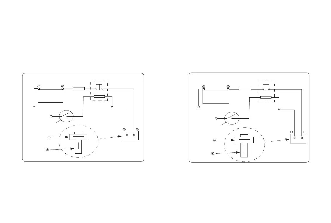
12 Volt Excavator connection diagram to 12V
2 Speed Drive Unit
24 Volt Excavator connection diagram to 24V
2 Speed Drive Unit
• Connect pin 30 of relay via 10 Amp fuse to battery positive terminal.
• Connect pin 86 of relay to an ignition source.
• Connect pin 85 of relay to chassis ground or battery ground terminal.
• Connect pin 87 of relay to two pin plug to connect to 2 Speed
controller harness (this connection point is tagged “supply”).
• Connect an earth to the two pin plug to connect to 2 Speed controller
harness.
2 Speed Drives
The 2 Speed drive can be supplied in either a 12V or 24V system as per customer request. There are 2 ways to
electrically power the drive unit.
(i) Hard wire from the machine battery
12 2 Speed Installations-Electrics
• Connect pin 30 of relay via 10 Amp fuse to battery.
• Connect pin 86 of relay to and ignition source.
• Connect pin 85 of relay to an earth point or earth of battery.
• Connect pin 87 of relay to positive terminal of the 2 pin plug.
• Connect an earth to the two pin plug to connect to the 2 Speed
controller harness.
IGNITION
SWITCH
BLACK NEGATIVE
RED POSITIVE
GROUND
GROUND
12 VOLT RELAY
12 VOLT
BATTERY
10 AMP FUSE
30
86 85
87
IGNITION
SWITCH
BLACK NEGATIVE
RED POSITIVE
GROUND
GROUND
24 VOLT RELAY
24 VOLT
BATTERY
10 AMP FUSE
30
86 85
87