Pin signals Pin signals for the XBee 3 micro module
Digi XBee® 3 RF Module Hardware Reference Manual
28
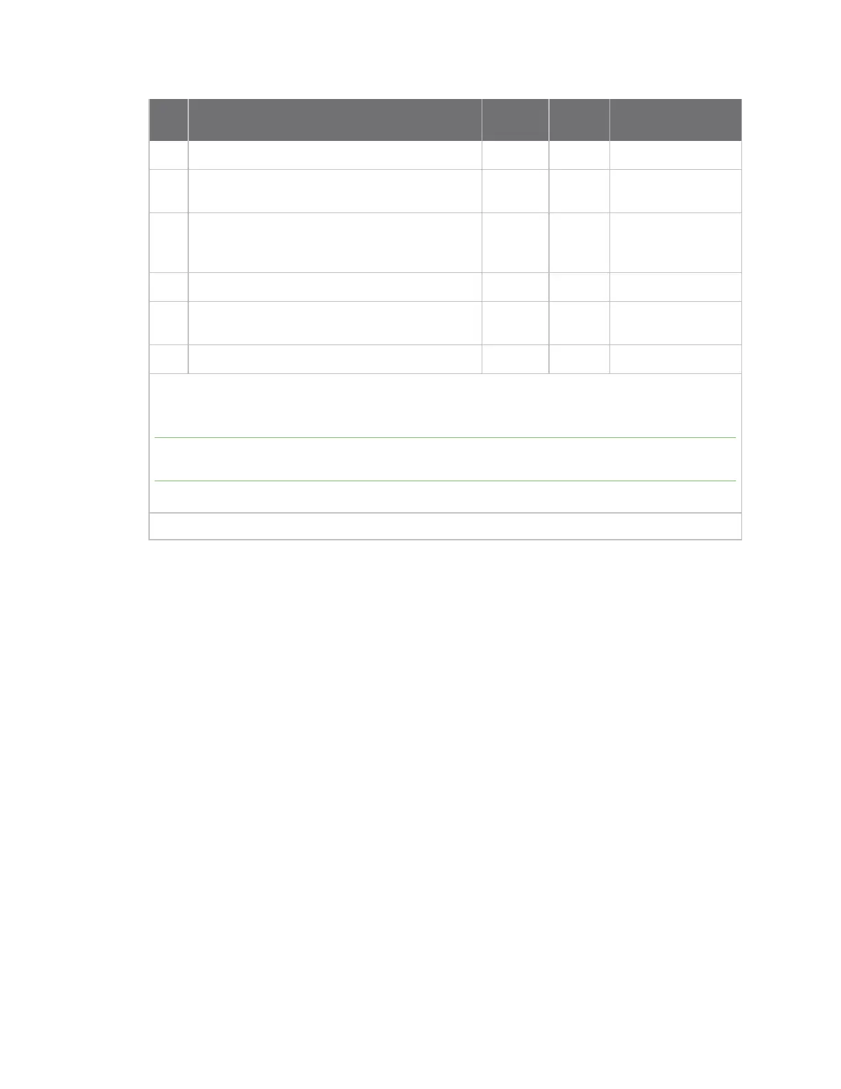
Pin# Name Direction
Default
state Description
29 AD2/DIO2 Both Disabled
Analog input/GPIO.
30 AD1/DIO1/I2C SCL Both Disabled
Analog
input/GPIO/I2C SCL.
31 AD0 /DIO0 Both Input Analog input / GPIO
/ Commissioning
button.
32 GND - - Ground.
33 RF Both - RF I/O for RF pad
variant.
34 GND - - Ground.
Signal direction is specified with respect to the device.
This is a complete list of functionalities. See the applicable software manual for available
functionalities.
Note There are three RF test points located on the bottom of the device. Do not connect these test
points. For more information, see Recommended footprint.
See Design notes for details on pin connections.
* The I2C functionality will be software enabled in a future release.

 Loading...


